Do you have a question about the Paradox NV35MR and is the answer not in the manual?
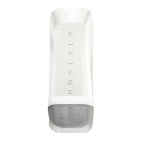
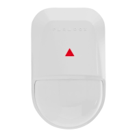
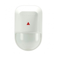
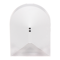
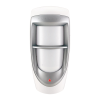
Overview of the NV35MR wireless detector and recommended installation for pet immunity.
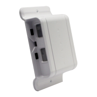
Step-by-step guide for removing covers, mounting the back cover, and attaching the main unit.
Details on setting sensitivity levels and DIP switch functions for PET/SHARP and anti-mask modes.
Procedure for performing a walk-test and final closure of the detector's front cover.
Visual representation of detection coverage in PET Mode and SHARP Mode from side and top views.
Table detailing the function and status indication of the detector's LEDs for various events.
Key technical details including detection range, input voltage, current, and compatibility.
Information on operating temperature, humidity, dimensions, weight, and RF frequency.
Details regarding product certifications, including safety standards and classification.
Information on the product's limited warranty and where to find full details.
Notice regarding applicable US, Canadian, and international patents and trademarks.
The Paradox NV35MR is a wireless dual-band detector designed for both outdoor and indoor use, specifically for windows and sliding doors. It offers advanced protection with anti-masking capabilities and pet immunity, making it suitable for professional security needs.
The NV35MR functions as a security sensor that detects movement within its field of view. It operates in two primary modes: Pet Immunity mode and Sharp mode. In Pet Immunity mode, the detector is designed to ignore small animals, such as birds, cats, and small dogs (approximately 50cm in size), preventing false alarms. This mode is particularly useful when the detector is installed outdoors within the frame of windows and doors, where pets might access the window sill. Sharp mode, on the other hand, provides a more sensitive detection, suitable for environments where pet immunity is not required or when a broader range of motion detection is desired.
The device incorporates active IR detection for anti-masking, which means it can detect attempts to block its field of view, such as by spraying liquid or placing an object within 30cm of the sensor. This feature enhances the security by preventing potential intruders from disabling the detector.
The NV35MR is a wireless device, communicating via dual-band RF frequencies (433.92 MHz and 868.35 MHz, with 433.92 MHz being standard for USA and Canada). This wireless capability simplifies installation and allows for flexible placement without the need for extensive wiring. It is compatible with Paradox RTX3 and Magellan systems.
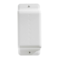
Installation of the NV35MR involves several straightforward steps. First, the front cover is removed by opening a captive screw. The main unit is then detached from the back cover by releasing two snap-lock mechanisms. The back cover is mounted onto the window frame or wall using screws, ensuring at least 4 cm (1.5 in.) of clearance from any window or shutter to avoid obstruction. After mounting the back cover, the main unit is reattached, ensuring the locks snap closed. Two AA alkaline batteries are then inserted to power the device.
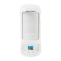
Detector settings can be configured using DIP switches and a sensitivity trimmer. Users can select between LED on/off, Pet Immunity mode or Sharp mode, and anti-masking on/off. The anti-masking sensitivity can also be set to high or low. The sensitivity trimmer allows for fine-tuning the detection range, with options for 3m/5m, 5m/7m, and 7.5m/10m, depending on the chosen mode. The default sensitivity level is 2, indicated by 1-3 green LED flashes.
Once installed and configured, the front cover is replaced and the captive screw is closed. It is crucial not to obscure the detector's field of view to ensure optimal performance. For SP panels, the tamper function must be enabled.
To verify successful installation, a walk-test should be performed. This involves walking slowly across the far end of the detection range to confirm that the device detects movement. The walk-test mode lasts for 5 minutes after the tamper screw is closed.
The NV35MR provides visual feedback through an LED status indicator. Different LED behaviors signify various device states:
The device is designed for outdoor use with an IP54 rating, indicating protection against dust and splashing water. It can operate in a wide temperature range from -35°C to +50°C and at 95% non-condensing relative humidity.
The NV35MR is designed for low maintenance. The battery life is approximately 3 years under typical use, powered by two 1.5VDC AA alkaline batteries. The device provides a low battery voltage signal when the voltage drops to 2.5V, alerting the user to replace the batteries.
The anti-masking feature helps in maintaining the device's operational integrity by detecting and signaling any attempts to obstruct its view, ensuring continuous protection.
For installation, an optional mounting bracket (part number: SB35) is available, offering flexibility in mounting options. The device is designed for easy access to batteries and settings, simplifying any necessary adjustments or replacements.
The NV35MR is a robust and reliable security solution, offering advanced detection capabilities with user-friendly installation and maintenance features, making it an excellent choice for securing windows and sliding doors.
| Microwave Range | Adjustable |
|---|---|
| Current Consumption (Alarm) | 18mA |
| Operating Temperature | -35°C to +50°C (-31°F to +122°F) |
| IP Rating | IP54 |
| Tamper Protection | Yes |
| Sensor Type | Dual Technology (PIR + Microwave) |
| Detection Method | PIR & Microwave |
| PIR Range | Up to 3m (10ft) |
| Power Supply | 9 to 16 VDC |
| Humidity | 95% max |
| Mounting | Wall |