TM40 Quick Install Guide
Printed in Canada | 09/2011
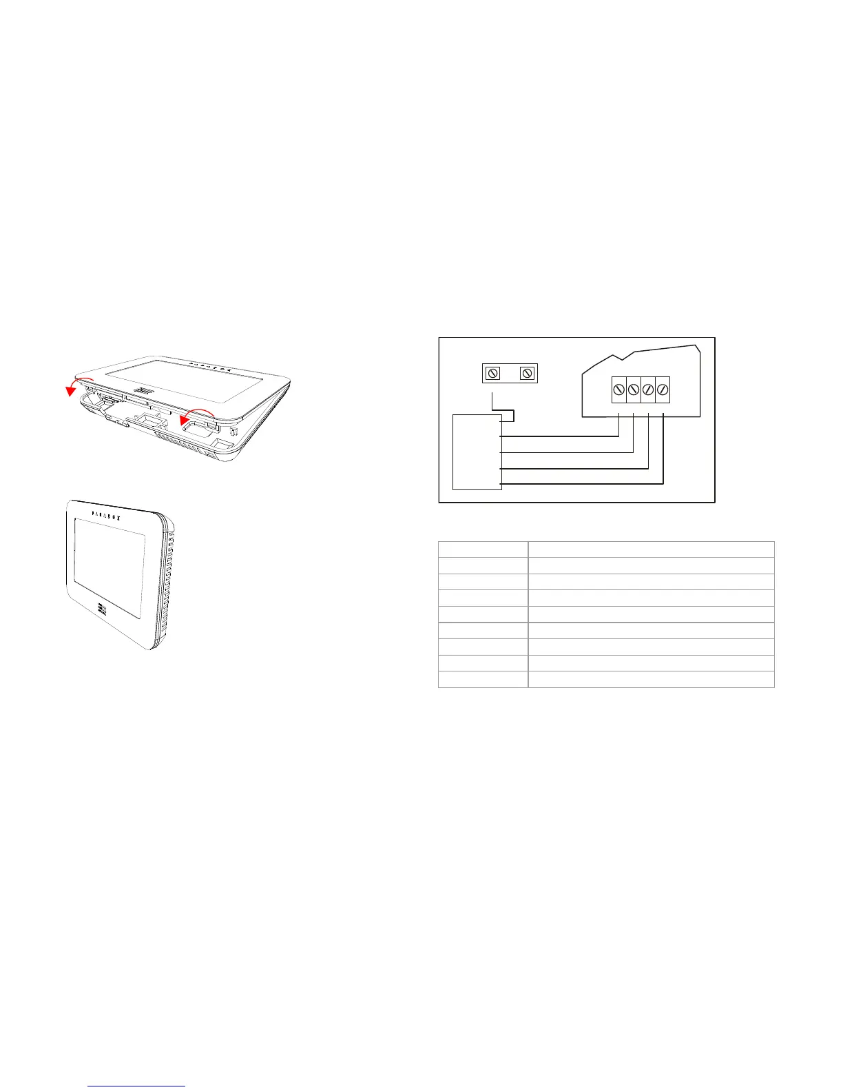
4. Secure the front housing assembly to the back plate by
snapping it into place.
The installation process is complete.
TM40 to Panel Connections
As shown in the Wiring Diagram, the red, black, green, and yellow
wires on the TM40 must be connected to their corresponding
labeled terminals on the control panel’s PCB. The blue wire is
connected to either a keypad zone or external temperature
sensor.
Wiring Diagram
Technical Specifications
Power Input 9 to 16 Vdc
Consumption 110 mA
Display 16-bit, color LCD; 5.4 x 9.5 cm (2.1 x 3.7 in.)
Resolution 480 x 272 pixels
Dimensions 12.4 x 8.1 x 1.6 cm (4.9 x 3.2 x 0.7 in.)
Weight 0.15 kg (0.33 lbs.)
Humidity 5-90%
Sensors Indoor temperature sensor
Standards Complies with EN 50131 Security Grade 3 Class II
Warranty: For complete warranty information on this product, please
refer to the Limited Warranty Statement found on the Web site
www.paradox.com/terms. Your use of the Paradox product signifies your
acceptance of all warranty terms and conditions.
© 2011 Paradox Ltd. All rights reserved. Specifications may change
without prior notice. www.paradox.com
 Loading...