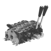
The Parker Gresen Model V10 Sectional Body Directional Control Valve is a robust hydraulic component designed for precise control of fluid power in various applications, particularly those requiring a sectional body design for flexibility and customization. This service manual provides comprehensive instructions for the maintenance, repair, and assembly of the valve, ensuring its continued reliable operation.
Function Description
The Model V10 valve serves as a directional control valve, meaning it directs the flow of hydraulic fluid to different parts of a hydraulic system, thereby controlling the movement and operation of actuators such as cylinders and motors. Its sectional body design allows for a modular approach, where individual work sections can be assembled together to create a valve bank tailored to specific application needs. This modularity enables users to configure the valve with different spool functions, positioners, and other features as required. The valve is designed to handle significant operating pressures, making it suitable for demanding hydraulic tasks.
Usage Features
The Model V10 valve offers several features that enhance its usability and adaptability in various hydraulic systems:
- Sectional Body Design: This is a core feature, allowing for highly customizable valve configurations. Users can select the number and type of work sections, inlet covers, and outlet covers to match the exact requirements of their machinery. This modularity simplifies inventory management and allows for easy expansion or modification of the hydraulic system.
- Spool Options: The valve supports various spool types, including those for spring return and float positions. Different positioner options, such as 4-position and 5-position float spool positioners, provide precise control over actuator movement, including detent functions for holding a spool in a specific position without continuous operator input.
- Power Beyond Capability: For machines equipped with front loaders or other auxiliary functions, the valve can incorporate a power beyond sleeve. This feature allows hydraulic fluid to be routed to downstream components even when the main valve sections are in use, ensuring continuous operation of multiple functions.
- Handle and Joystick Assemblies: The valve can be operated via an extended handle assembly for direct manual control or a joystick assembly for more ergonomic and multi-axis control. The joystick adapter plate assembly further enhances the flexibility of control input, allowing for both right-hand and left-hand joystick installations.
- Work Port Relief Cavity Plug: This component is crucial for managing pressure within individual work ports, protecting actuators and other system components from overpressure conditions.
Maintenance Features
The service manual emphasizes several key aspects of maintenance to ensure the longevity and optimal performance of the Model V10 valve:
- Seal Kits: The availability of section seal kits and spool seal kits simplifies the replacement of worn or damaged seals, which are critical for preventing internal and external leakage. The manual provides detailed procedures for removing and installing spool seals, including important precautions regarding lubrication and proper fit.
- Back-Up Rings: Special attention is given to back-up rings, which are used in conjunction with O-rings to prevent extrusion under high pressure. The manual describes how to prepare and install continuous back-up rings, noting that factory-installed rings typically do not need replacement unless damaged.
- Torque Specifications: Precise torque values are provided for all fasteners, including assembly studs, bonnet screws, and cavity plugs. Adhering to these specifications is crucial for preventing spool bind, seal extrusion, and ensuring the structural integrity of the valve assembly. The manual differentiates between torque values for dry and oiled tie bolts.
- Lubrication Guidelines: Specific instructions are given for lubricating certain components, such as the handle rod and detent balls within positioners, using NLGI #2 Heavy Duty General Purpose Grease. Conversely, the manual explicitly states not to lubricate O-ring section seals prior to installation to prevent spool bind.
- Thread Locking Adhesive: For critical fasteners, such as spool screws and lock nuts, the use of thread locking adhesives (e.g., Loctite No. 242 Blue or Loctite No. 262 Red) is specified to prevent loosening due to vibration or operational stresses.
- Detailed Assembly Procedures: The manual includes step-by-step instructions and clear diagrams for disassembling and reassembling various components, such as spool positioners, handle assemblies, and joystick assemblies. This level of detail enables technicians to perform repairs accurately and efficiently.
- Identification of Parts: Each component is clearly identified with a reference number and description, often accompanied by a quantity list, which aids in ordering replacement parts and ensures correct assembly.
- Filtration Requirements: While specific values are not to be included here, the manual implicitly highlights the importance of maintaining clean hydraulic fluid by specifying minimum filtration requirements. This is a critical preventative maintenance aspect to protect all hydraulic components, including the valve, from contamination-induced wear.
By following the guidelines and procedures outlined in the service manual, users can effectively maintain, troubleshoot, and repair their Parker Gresen Model V10 Directional Control Valve, ensuring its long-term performance and reliability in demanding hydraulic applications.