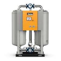
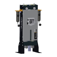
This document describes the Parker Zander KE-MT 120-600 Adsorption Dryer, an industrial device designed for drying compressed air.
Function Description
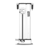
The KE-MT 120-600 adsorption dryer is engineered to remove humidity from compressed air, making it suitable for industrial applications. The dryer operates by utilizing two vessels, each filled with a highly porous drying agent. This agent absorbs humidity from the compressed air, much like a sponge. Once saturated, the stored humidity is then removed from the drying agent and released into the ambient environment during a regeneration process. The two vessels alternate between different operating modes: while one vessel dehumidifies compressed air (adsorption), the other regenerates its drying agent for subsequent use. This parallel operation ensures a continuous supply of dry compressed air.
The drying process begins with humid compressed air entering the dryer's inlet from a compressor. This air flows upwards through the adsorption vessel, which is under pressure. As the air passes through the drying agent, it is dehumidified. The dry compressed air is then supplied to the pipe network via the dryer's outlet.
Simultaneously, the other vessel undergoes regeneration, preparing it to absorb humidity again. Regeneration is divided into three phases:
- Expansion Phase: The pressure in the regenerating chamber is released to ambient pressure via a muffler within a few seconds. This rapid outflow of compressed air creates a sudden, powerful flow noise.
- Dehumidification Phase: Dried compressed air, bled through an orifice plate, is fed through the depressurized chamber. This air picks up the humidity stored in the drying agent and expels it into the atmosphere through the muffler.
- Pressure Build-up Phase: After dehumidification, the regenerated vessel is repressurized to operating pressure. This allows for a smooth switchover from regeneration to adsorption at the operating pressure level.
For dryers equipped with the optional dewpoint-sensing control, a Standby Phase follows regeneration. In this phase, the fully regenerated vessel is ready for adsorption. The system switches to this vessel once the measured dewpoint at the compressed air outlet reaches a preset value.
Switchover occurs when the drying agent in the adsorbing chamber has absorbed a sufficient level of humidity. The process then repeats, with the vessels exchanging roles for adsorption and regeneration.
Important Technical Specifications
The KE-MT 120-600 series offers various models with different capacities and dimensions. Key technical data includes:
- Fluid Group: 2
- Max. Operating Pressure: 10 bar
- Min. Operating Pressure: 6 bar
- Min. Ambient Temperature: ≥ +1°C (33.8°F)
- Max. Ambient Temperature: ≤ +50°C (122°F)
- Noise Level: 65 - 95 dB(A) (relative to free field measurement, 1 m surrounding field)
- Protection Class: IP 65
Performance details for the KE-MT 120-600 series (relative to 1 bar (abs.) and 20 °C (68 °F) at 7 bar operating pressure and a feed temperature of 35 °C (95 °F)):
| Type |
Capacity* (m³/h) |
Length (mm) |
Height (mm) |
Width (mm) |
Weight (kg) |
| KE-MT 120 |
1200 |
1060 |
2080 |
840 |
640 |
| KE-MT 150 |
1550 |
1270 |
2120 |
900 |
830 |
| KE-MT 200 |
2000 |
1350 |
2160 |
990 |
955 |
| KE-MT 250 |
2500 |
1530 |
2210 |
1040 |
1075 |
| KE-MT 300 |
3000 |
1600 |
2255 |
1100 |
1500 |
| KE-MT 380 |
3800 |
1875 |
2385 |
1200 |
1990 |
| KE-MT 500 |
4850 |
1925 |
2660 |
1250 |
2410 |
| KE-MT 600 |
6100 |
2160 |
2820 |
1565 |
2850 |
Usage Features
The dryer is primarily intended for indoor installation, protected from moisture, with an ambient temperature range of +1.5 °C to +50 °C. Proper spacing (minimum 1m at top and sides) is required for maintenance access.
Control System and Operating Modes:
The dryer features an ON/OFF switch (2) and a display panel with LEDs and a digital display.
- ON/OFF Switch:
- Position 0: Power supply disconnected, dryer switched off, expansion valves normally closed.
- Position I: Dryer switched on, operates in fixed cycle (time-controlled) mode.
- Position II: Dryer switched on, operates with compressor synchronization and/or dewpoint-sensing control in variable cycle mode. This position is only relevant for optional features.
- Display Panel:
- LED Power (1): Illuminates when the dryer is switched on.
- Flow Diagram (2): Four LEDs indicate current operating phases (Adsorption B1/B2, Regeneration 1/2).
- Digital Display (3): Shows individual program steps and remaining time.
- Vessel Pressure Gauge: Displays operating overpressure. During adsorption, it should show nominal operating overpressure. During regeneration, it should decrease to 0 bar during expansion and dehumidification, then rise back to operating pressure during pressure build-up. A "dam pressure" exceeding 0.3 bar during regeneration indicates a potential issue.
Optional Features:
- Start-up Device: Ensures pressure build-up and adsorption when filling an empty compressed air reservoir or system.
- Outside Installation: Requires specific technical design measures due to environmental factors like humidity, corrosion, and freezing temperatures.
- Auxiliary Heater: Recommended for installation sites below +1 °C to prevent freezing of components.
- Bypass Line: Allows the compressed air system to continue operating during dryer maintenance, though the air will not be dried.
- Signalling Contacts of Control System: Provides digital input for synchronized operation with a compressor and an optional operation signaling contact for external monitoring and dewpoint alarms.
- Compressor Synchronization: Reduces energy costs by synchronizing dryer regeneration with compressor operation. Regeneration continues until completion even if the compressor stops, preventing premature drying agent degradation.
- Dewpoint-sensing Control: Allows for variable cycle operation based on the measured dewpoint, optimizing regeneration based on drying agent saturation.
- Pneumatic Control: An alternative to electronic control, suitable for hazardous areas.
- Regeneration Gas Recirculation: Ensures regeneration continues when the compressor is off, provided sufficient compressed air is available downstream.
- Paint Compatible Design: Features seals and filters free of grease and silicon for high-quality compressed air in paint shop applications.
- Preliminary and After-filters: Recommended to protect the desiccant from dirt, oil, and water droplets (pre-filter) and prevent desiccant particle contamination in the dried air (after-filter).
- Condensate Drain Systems: Installed in preliminary/after-filters to drain collected water, available as level-controlled or time-controlled systems.
Maintenance Features
The dryer requires regular maintenance to ensure optimal performance and longevity.
Daily Maintenance Tasks:
- Visual and Function Check: Inspect for external damage, unusual noise, and eliminate any defects. If "SEr." (service) is displayed, contact service personnel.
- Clean Dryer: Remove dust with a dry or moist cloth.
- Check Dam Pressure: Verify pressure gauges show 0 bar after depressurization. If dam pressure exceeds 0.3 bar, investigate for blocked mufflers, contaminated dust sieves, or old drying agent.
Maintenance Work to be Completed Every 12 Months:
- Renew Filter Element of Control Air Filter: Replace the filter element to ensure proper valve actuator function.
- Renew Mufflers: Replace mufflers every 12 months and after each desiccant change to prevent blockage and potential bursting due to overpressure.
- Renew Dewpoint Sensor (optional): Replace annually for precise dewpoint measurement.
- Replacing Pilot Valves: Part of every service kit, to be replaced every 12 months.
Maintenance Work to be Completed Every 48 Months:
- Pressure Vessel Inspection: In accordance with national regulations, an independent supervisory office may require inspection. This involves removing the drying agent and checking all fittings, sieve bottoms, and gaskets.
- Renew Drying Agent: Typically every 3 to 5 years, but depends on compressed air contamination. Oil, dust, and dirt particles reduce the drying agent's effective surface.
- Replacing Dust Filters: Replace along with the drying agent to prevent back pressure fluctuations.
- Replacing Solenoids: Included in 48-month service kits, to be replaced every 4 years.
Fault Identification and Elimination:
The manual provides a comprehensive table of possible faults, their causes, and remedies, indicating whether the task can be performed by specialized personnel or a service technician.
Service Counter Reset (using Dongle):
When the "SEr." message flashes on the Multitronic controller display (after 8000 operating hours), servicing is due. A dongle (included with service kits) can be used to reset the service counter to 0. This involves switching off the controller, opening the lid, slotting the dongle into the X9 PC interface, pressing and holding the S3 reset key, and then switching the controller back on. Each dongle is single-use.