Bulletin 4391-B400S
EXACTOL
®
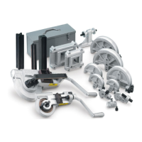
400 Series Tube Benders
7
Parker Hannifin Corporation
Tube Fittings Division
Columbus, OH
www.parker.com/tfd
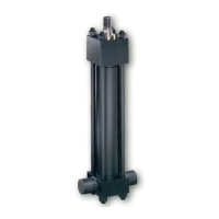
Thin Wall Tube Bending with Mandrel Equipment
Step 3: Select Radius Block Mandrel and Rod
Select the proper radius block according to the chart as described in Step
2 on page 4. Select the Mandrel according to the outside diameter and
wall thickness of the tubing. The selected Mandrel is screwed onto one
end of the mandrel rod. The other end of the mandrel rod is screwed onto
the adapter and then into the rod stop assembly.
Step 1: Mount Bender in Adapter Assembly
For mandrel bending, it is necessary to in-
stall the bender in a bench mounting adapter
assembly. Locate the adapter assembly
front mounting holes about 3” from the front
edge of the bench, with T slot front to back
and scale on the right. Secure the bender in
the adapter assembly by tightening the flat
head screws in the bottom of the adapter
slide. Then place the bender in the mounting
assembly with the axis of its drive handle
shaft parallel with the T slot. This places the
handle end of the bender towards the opera-
tor with the adapter scale to the right. (The
adapter slide and scale will be used later to
align the bender with the mandrel).
Step 2: Install Mandrel Rod Stop Assembly
Draw a centerline for the mandrel rod stop assembly and height adapter
to the right of the reference mark (A) on the adapter assembly. Position
the rod-stop assembly and height adapter on this line with the single
mounting hole nearest the bender.
Step 4: Adjust Mandrel
For average bending, the mandrel should be
adjusted so that the scribed line on its cir-
cumference is 5/8” behind the 0 mark on the
radius block. Make this adjustment by turning
locknuts on the mandrel rod stop assembly.
The mandrel may be moved forward slightly
to produce a more nearly perfect round
cross-section of the bent tube, or it may be
moved slightly backward to ease the bending
effort. However, extremes in either direction
may cause wrinkling, breaking, or flattening
of the tube.
 Loading...