English
6 / 8
ICEP003-005 (60Hz)
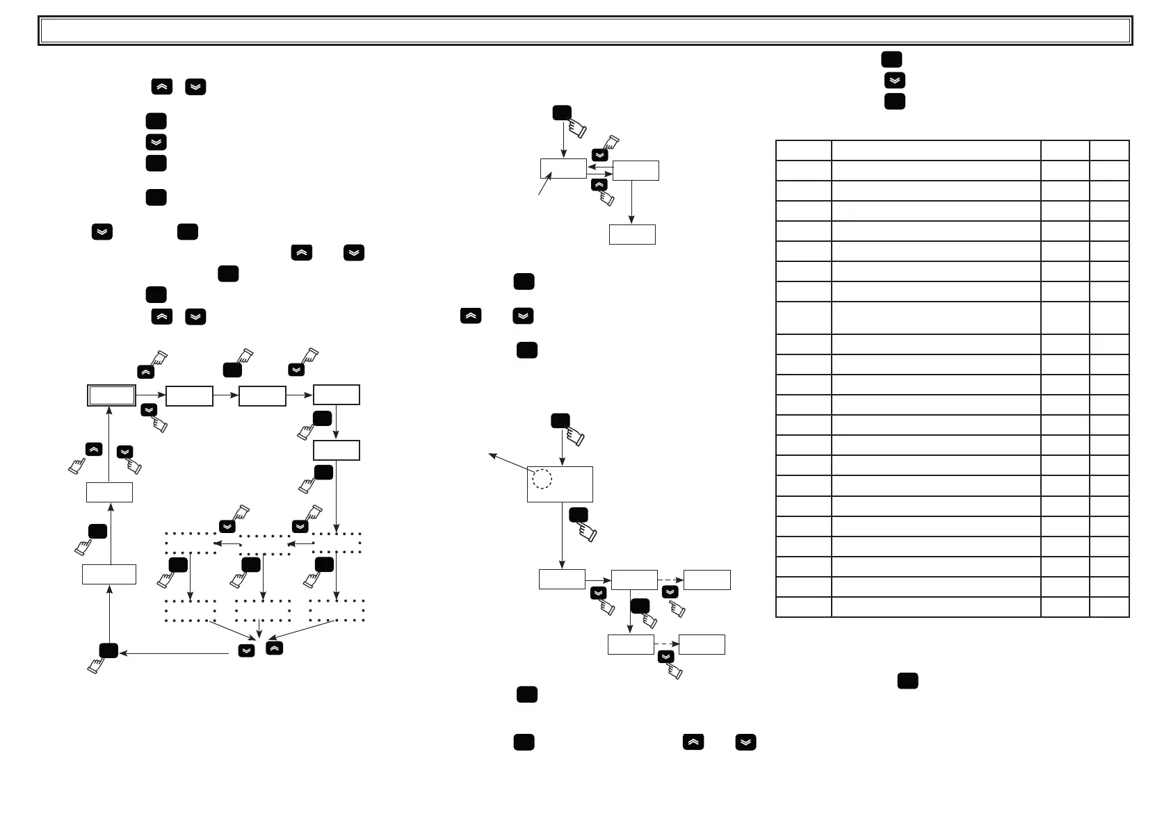
4.6 Setting clock/date.
(see g. 1/3)
1. Press the buttons “
” “ ”, together to enter in the menu
“FrEE”.
2. Press the button “
set
” to enter in the menu “Ai”.
3. Press the button “
” to enter in the il menu “CL”.
4. Press the button “
set
” to enter and visualize the parameter
“HOUr”.
5. Press the button “
set
” until the ashes of the parameter “HOUr”.
6. Select the ashing parameter “HOUr”/“dAtE”/“4EAr” using the
button “
” and press “
set
” to enter.
7. Change the ashing value using the buttons “
”and “ ” (up
and down) and press the button “
set
” to con rm.
8. Press the button “
esc
” to return to the menu “FrEE”.
9. Press the buttons “
” “ ” together to exit.
Fig.3
set
dr4
FrEE
Ai
CL
set
HOUr
4EAr
set
set
01.09
set
2015
17.15
set
FrEE
HOUr
dAtE
set
3 sec.
18.20
esc
! The memory of the “clock / date” has a maximum duration of
three days, so if the controller is left without power for more than
three days, the data set hour / month / year are lost.
Adjust the clock at the start up of the machine, and whenever
necessary.
4.7 Visualization of temperature probes B1,B2
(see g.1/4)
Fig.4
set
12.5
b1
b2
3
sec.
5.0
1. Turn the main swicth (QS) to “ON” and wait for the “OFF” visualiza-
tion.
2. Press the button “
set
” to start up.
3. The display shows the temperature of the probe B1.
4. Using “
”and “ ” buttons select the probe (B2), wait for 3
seconds to see the temperature value.
5. Press the button “
esc
” to exit
4.8 Alarms management
(see g.1/5)
Fig.5
set
set
!
23.5
Pb
AL
set
Er__ Er__
ALARM
1. Press the button “
set
” to start up.
2.
! Alarm ON (led on: red).
3. Press the button “
set
” to enter in the menu, using “ ”and “ ”
buttons select the parameter “ AL” .
4. Press the button “
set
” to see the alarm code.
5. Press the button “
” to see the next code.
6. Press the button “
esc
” to exit.
4.8.1 Analog /Digital input alarms
CODICE DESCRIZIONE AZIONE RESET
Er01
Sensor B1 cutout or broken Alarm A
Er02
Sensor B2 cutout or broken Alarm A
Er03
Sensor B3 cutout or broken Alarm A
Er04
High pressure Alarm M
Er05
Low pressure Alarm M
Er06
Pump thermal cutout Alarm M
Er07
Low water level Alarm M
Er08
High pressure trasducer cutout or
broken
Alarm A
Er10
Sensor B4 cutout or broken Warning M
Er12
Compressor thermal * Alarm M
Er14
High temperature sensor B1 Alarm A
Er15
Low temperature sensor B1 Alarm A
Er16
High temperature sensor B2 Alarm A
Er17
Low temperature sensor B2 Alarm A
Er18
High temperature sensor B3 Alarm A
Er19
Low temperature sensor B3 Alarm A
Er20
Antifreeze Alarm A
Er21
Exceeded compressor working hours Warning A
Er23
Phase monitor Alarm M
Er24
Exceeded unit working hours Warning A
Er25
Communication expansion Alarm A
Er26
Controller memory Warning A
*
! (Only oil model)
If the evaporator temperature falls below 5°C for more than 120s
then an alarm “
Er12 “ will occur, blocking the unit.
!Press the button “
esc
” to reset alarms (5sec).