Do you have a question about the Parker IQAN-MD4 and is the answer not in the manual?
Explains warning symbols and their importance for safety.
Lists related documentation for the IQAN module system.
Emphasizes importance of knowledge and reading relevant sections before work.
Warns about injury from control system design and need for safety principles.
Guides personnel on initial start, maintenance, and troubleshooting procedures.
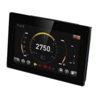
Introduces the IQAN-MD4 as a display and bus master module.
Describes the IQAN-MD4 as a central unit with CAN buses and Ethernet ports.
Details voltage and digital inputs, and digital outputs of the IQAN-MD4.
Explains CAN and Ethernet communication for applications and diagnostics.
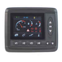
Covers the display, touch function, and physical aspects of the human interface.
Explains self-checks for voltage, memory, and software execution for improved safety.
Describes how IQAN modules handle CAN-bus communication interruptions.
Details the current check performed on proportional outputs for error detection.
Emphasizes the importance of properly installing emergency stop functionality.
Provides instructions for mounting the IQAN module in various configurations.
Details panel mounting with recommended thickness and screw types.
Explains using brackets for flexible display positioning with ball or tilt/swivel mounts.
Advises on positioning for accessibility, cable protection, and environmental factors.
Describes specifications for connectors C1 and C2, including kit and part numbers.
Lists pin numbers, symbols, and functions for connector C1.
Lists pin numbers, functions, and alternative functions for connector C2.
Details pin assignments for Ethernet connectors C3 and C4.
Advises on accessible emergency stop placement and its function.
Details connecting supply voltage to +BAT and -BAT with fuse protection.
Explains the requirement for a separate power connection for the real-time clock.
Discusses module protection against polarity reversal and over-voltage.
Explains using ID-Tags for unique addressing in multi-master systems.
Describes how ID-Tags assign addresses and enable project loading.
Details connecting to the CAN bus for diagnostics and required termination resistors.
Explains using Ethernet Port A (C3) for diagnostic communication and application uploads.
Covers connecting external video sources via Ethernet Port B (C4).
Explains the internal voltage regulator generating VREF for sensors.
Details connecting 0-5 Vdc sensors to voltage inputs, including signal ranges.
Explains connecting 3-wire sensors like temperature, pressure, and Hall-effect levers.
Describes connecting 2-wire PTC temperature sensors with pull-up resistors.
Details connecting switches to voltage inputs for digital on/off signals.
Explains connecting switches to voltage inputs using +BAT for digital signals.
Explains using the DPCNT input for counting pulses, bi-directionally.
Details connecting directional pulse count sensors to DPCNT+ and DPCNT- positions.
Describes low-side digital outputs for driving small loads like lamps and buzzers.
Provides instructions for actions during the initial start of the control system.
Details preparations for system start, including safety checks and module power status.
Guides on starting the engine and calibrating input/output signals.
Presents absolute maximum and environmental ratings for the IQAN-MD4.
Lists system specs including weight, temperature, voltage, and memory.
Details specs for the 7-inch LCD display, including resolution and brightness.
Details specs for the 5.7-inch LCD display, including resolution and brightness.
Details specs for the 10.1-inch LCD display, including resolution and brightness.
Provides details on VREF output voltage, drift, load current, and protection.
Lists VIN specs, including full scale, resolution, impedance, and accuracy.
Details DIN specs, including logic levels, hysteresis, and input impedance.
Covers DPCNT input specs, including frequency range and pulse width.
Lists DOUT specs, including maximum load, minimum load, and protection.
Details CAN bus specs, including number of buses and bus speed.
Covers Ethernet specs, including ports, network interface, and IP configuration.
Explains how faults are presented on the display and potential hazards.
Introduces tables detailing possible failures for module subsystems.
Lists CAN interface failure modes and their effects on communication and outputs.
Lists VREF failure modes, their causes, and effects on VIN.
Lists VIN failure modes, their causes, and effects on the system.
Lists DIN failure modes and their effects on module operation.
Provides dimensional drawings and mounting hole details for the IQAN-MD4-7.
Provides dimensional drawings and mounting hole details for the IQAN-MD4-5.
Provides dimensional drawings and mounting hole details for the IQAN-MD4-10.
Shows dimensions and mounting options for the IQAN-MD4 bracket.
| Display Type | TFT LCD |
|---|---|
| Resolution | 800 x 480 pixels |
| CAN Channels | 2 |
| Video Inputs | 2 |
| Touchscreen | Yes |
| Display Size | 7 inches |
| Supply Voltage | 9-32 VDC |
| Protection Rating | IP65 |
| Storage Temperature | -40°C to 85°C |
| Power Supply | 9 to 32 VDC |
| Communication Ports | USB |