-- 4 --
and seek medical attention. An antivibration
system does not guarantee the avoidance of
these problems. Users who operate power tools
on a continual and regular basis must monitor
closely their physical condition and the condition
of this tool.
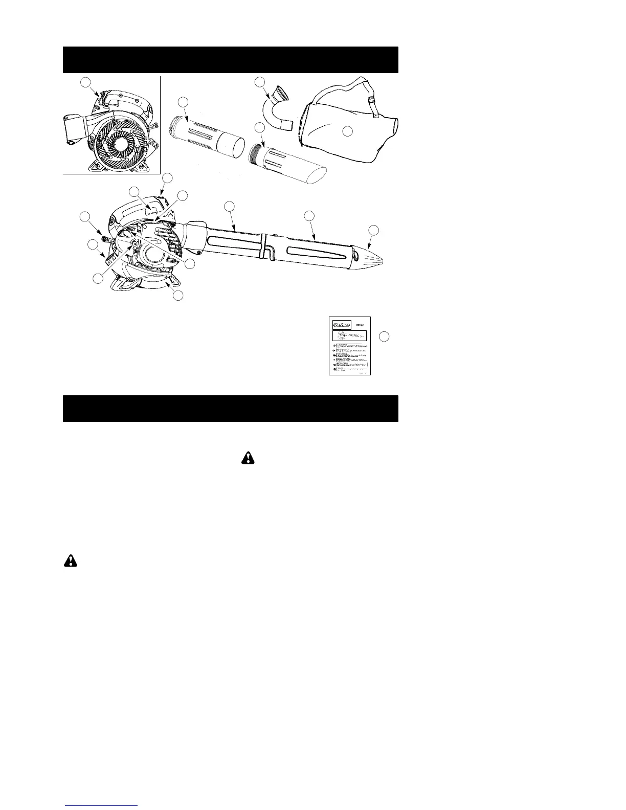
WHAT IS WHAT?
1. Throttle trigger 10. Lower blower tube
2. STOP switch 11. High--speed nozzle
3. Primer button 12. Elbow tube
4. Start lever 13. V acuum bag
5. Fuel cap 14. Upper vacuum tube
6. Starter rope 15. Lower vacuum tube
7. Vacuum handle 16. Throttle position lever
8. Spark plug 17. Instruction manual
9. Upper blower tube
WHAT IS WHAT?
17
14
12
15
10
11
9
8
2
1
6
3
5
16
4
7
13
ASSEMBLY
CARTON CONT ENT S
Check carton contents against the foll owing list.
S Blower
S Upper blower tube
S Lower blower tube
S High velocity nozzle
S Elbow tube
S Vacuum bag
S Upper vacuum tube
S Lower vacuum tube
S Screw for vacuum tube assembly
NOTE: It is normal for the fuel filter to rattle
in the empty fuel tank.
ASSEMBLY
WARNING: Stop engine and be sure
the impeller blades have stopped turning be-
fore opening the vacuum inlet door or at-
tempting to insert or remove the vacuum or
blower tubes. The rotating blades can cause
serious injury. Always disconnect the spark
plug before performing maintenance or ac-
cessing movable parts.
WARNING: If received assembled,
repeat all steps to ensure your unit is properly
assembled and all fasteners are secure. Fol-
low allsafety information in the manual andon
the unit.
D A standard screwdriver is required for as-
sembly.
BLOWER ASSEMBLY
BLOWER T UBE ASSEMBLY
1. Align the rib on the upper blower tube with
the groove in the blower outlet; slide the
tube into place.
NOTE: The tube clamp bolt must be loose
enough to allow blower tube to be inserted in
blower outlet. Loosen the bolt by turning coun-
terclockwise (do not remove nuts).