h/e Apparatus and h/e Apparatus Accessory Kit 012-04049J
6
®
14
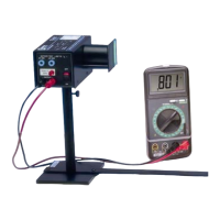
. Press the “PUSH TO ZERO” button on the side panel
of the h/e Apparatus to discharge any accumulated po-
tential in the unit's electronics. This will assure the Ap-
paratus records only the potential of the light you are
measuring. Note that the output voltage will drift with
the absence of light on the photodiode.
15
. Read the output voltage on your digital voltmeter. It is
a direct measurement of the stopping potential for the
photoelectrons. (See Theory of Operation in the Tech-
nical Information section of the manual for an expla-
nation of the measurement.)
➤ NOTE: For some apparatus, the stopping poten-
tial will temporarily read high and then drop down
to the actual stopping potential voltage.
All values except wavelength for yellow line are
from Handbook of Chemistry and Physics, 46th ed.
The wavelength of the yellow was determined ex-
perimentally using a 600 line/mm grating.
NOTE: The yellow line is actually a doublet
with wavelengths of 578 and 580mm.
Yellow 5.18672E+14 578
Green 5.48996E+14 546.074
Blue 6.87858E+14 435.835
Violet 7.40858E+14 404.656
Ultraviolet 8.20264E+14 365.483
Color Frequency (Hz) Wavelength (nm)
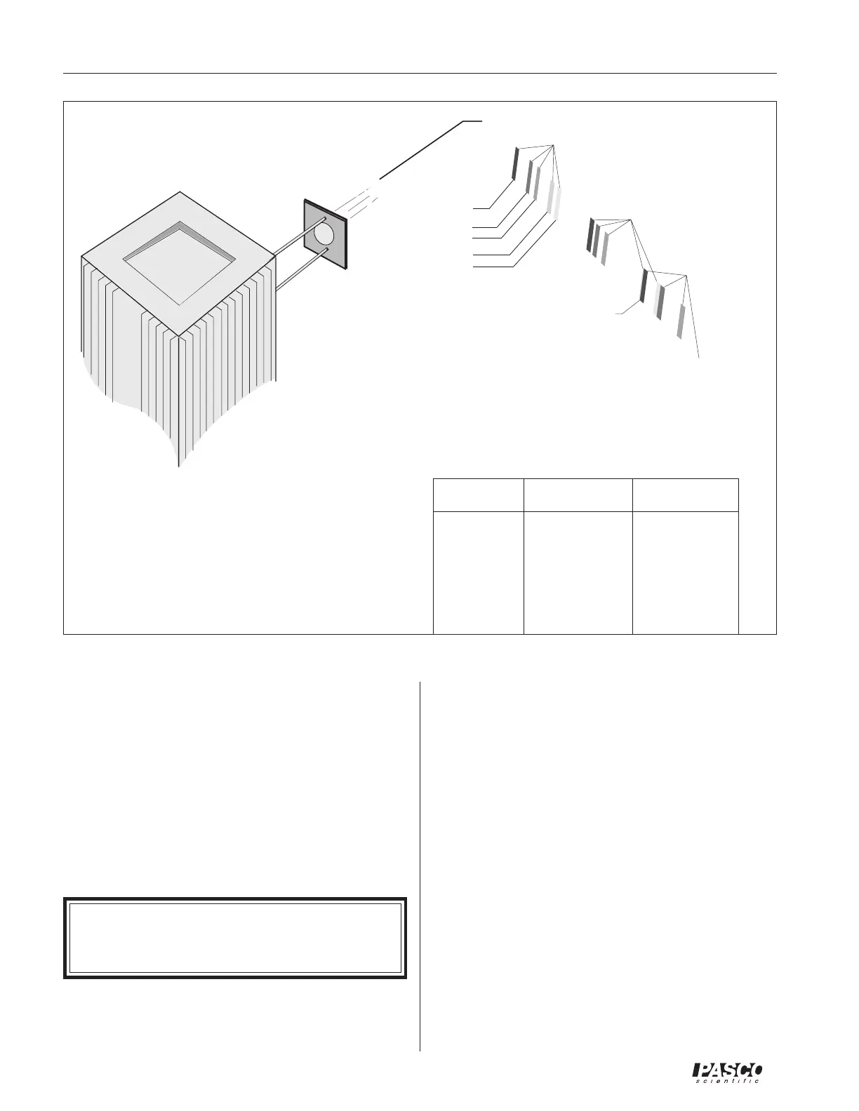
Figure 10. The Three Orders of Light Gradients
Using the Filters
The (AP-9368) h/e Apparatus includes three filters: one
Green and one Yellow, plus a Variable Transmission Filter.
The filter frames have magnetic strips and mount to the out-
side of the White Reflective Mask of the h/e Apparatus.
Use the green and yellow filters when you're using the
green and yellow spectral lines. These filters limit higher
frequencies of light from entering the h/e Apparatus. This
prevents ambient room light from interfering with the
lower energy yellow and green light and masking the true
results. It also blocks the higher frequency ultraviolet light
from the higher order spectra which may overlap with
lower orders of yellow and green.
The Variable Transmission Filter consists of computer-
generated patterns of dots and lines that vary the intensity
(not the frequency) of the incident light. The relative trans-
mission percentages are 100%, 80%, 60%, 40%, and 20%.
1st Order
2nd Order
Ultraviolet
3rd Order
Violet
Blue
Green
Yello w
White
Green & Yellow Spectral lines
in 3rd Order are not Visible.
2nd and 3rd Order Overlap