Hardware connections
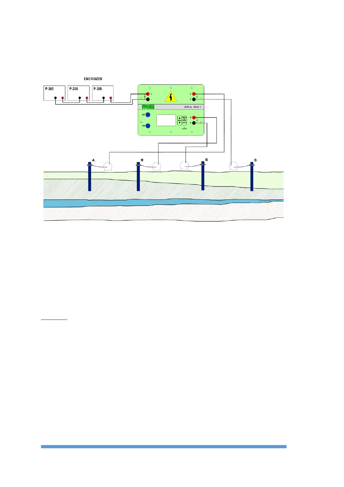
FIGURE 1 - HARDWARE CONNECTIONS
Figure 13 shows the connection diagram of the various hardware elements to the GEA
RM1 instrument. To the left at the top of the panel are the connection connectors for the
energizers (TX + and -), top right the connectors for the peaks of current input in the
ground (A and B), bottom right there are the connectors for measuring the ground voltage
(M and N), bottom left we find the USB connector for connection to the PC and the
internal battery charge and the EXT expansion connector that allows you to connect
external accessories.
Attention: when setting up the connections always pay the utmost attention to the
electrical risks, make the connections always with the energizer turned off and
disconnected; before starting the measurements, make sure that all the connections have
been correctly carried out and that everybody has moved away from the measuring pegs.
For the preparation and use of the non polarizable electrodes (optional), refer to the
instructions attached to them.
The energizer has its own user manual to be read.

 Loading...