TEST circuit diagram
Wiring diagram for GEORESISTIVITYMETER BOX TESTING
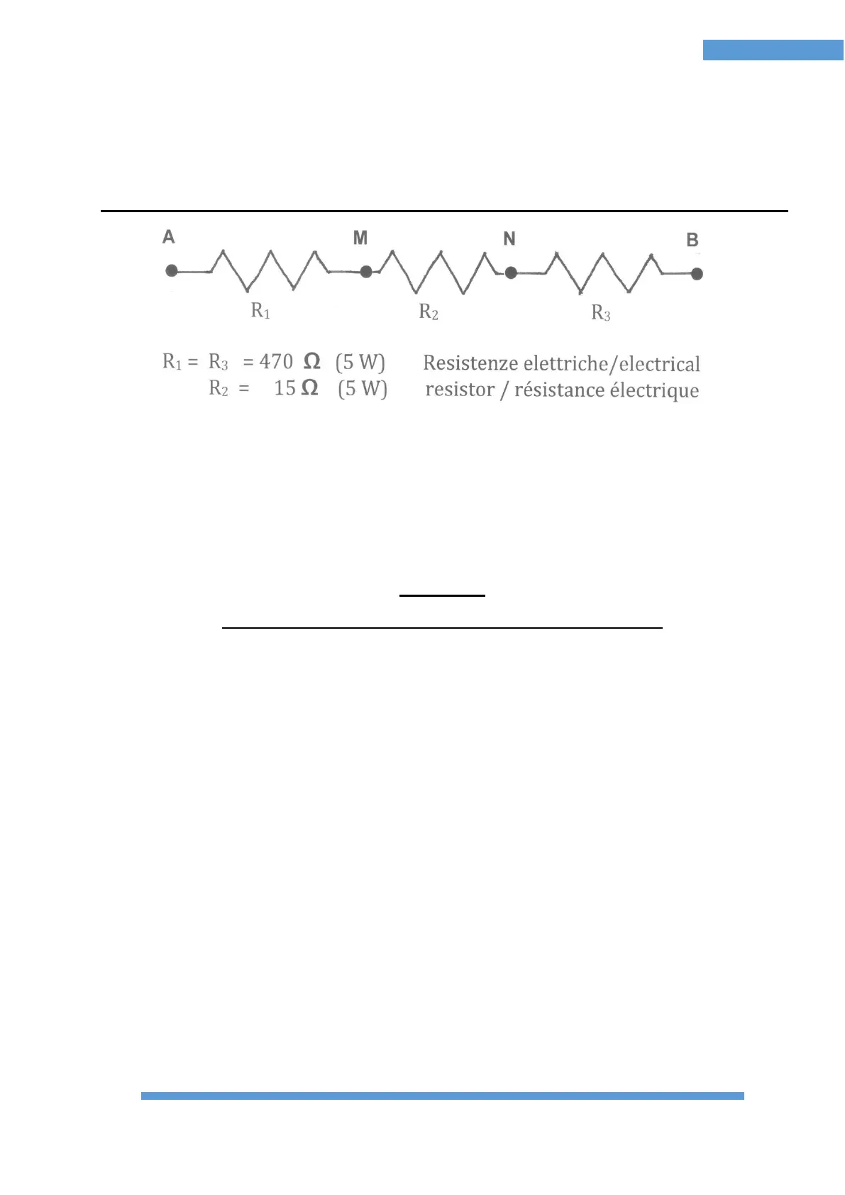
FIGURE 49 - ELECTRICAL DIAGRAM FOR TESTING BOX
Performing the measurement (after connecting A, B, M, N to the respective sockets on
the Resistivity Meter and the energizer to its socket) the ratio ΔV / I must be equal to the
value of R2 then 15 Ω (± 10%)
CAUTION:
the tensions produced by the energizer are potentially lethal!

 Loading...