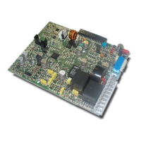
Ref. 11/676 PM2092/2-V
PMS2000 System4
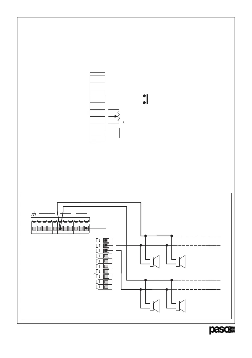
3. CONNESSIONI
La morsettiera ‘CONTROL I/O’ presente sul
pannello posteriore dell’amplificatore deve essere
utilizzata per effettuare le principali connessioni
della scheda PM2092/2-V. Il pannello superiore
dell’amplificatore è stato dotato di una legenda
riassuntiva delle connessioni (vedi fig. 3.1).
3. CONNECTIONS
The ‘CONTROL I/O’ terminal strip on the rear
panel of the amplifier has to be used to make the
main connections of the PM2092/2-V card.
A key summarising the connections has been
provided on the upper panel of the amplifier (see
Fig. 3.1).
TO POWER OUTPUT
TO SPEAKER LINE ‘B’
IN +
IN -
1
2
3
4
5
6
7
8
9
10
TO SPEAKER LINE ‘A’
LINE
REMOTE VOL.
INPUT
CONTROL I/O
min. 10 k LIN.Ω
RELAY CONTACT
RELAY CONTACT
I max 1A
V max 30V
• Collegamento alla linea altoparlanti
Collegare il terminale 1 della morsettiera ‘CONTROL
I/O’ all’uscita di potenza 100 V. La linea altoparlanti
‘A’ deve essere collegata al terminale 2; la linea
altoparlanti ‘B’ deve essere invece collegata al
terminale 3 (vedi figura 3.2).
• Connection to the loudspeakers line
Connect terminal 1 of the ‘CONTROL I/O’ terminal
strip to the 100 V power output. The loudspeaker
line ‘A’ has to be connected to terminal 2;
loudspeaker line ‘B’, on the other hand, must be
connected to terminal 3 (see Figure 3.2).
9
24V
Ω
0 48
50
V
70 100
-
-
++
1
C
O
N
T
R
O
L
I
O
2
3
4
5
6
7
8
10
MADE IN ITALY
SPEAKER
LINE ‘A’
SPEAKER
LINE ‘B’
Fig. 3.1
Fig. 3.2
(Relè segnalazione guasti)
(Fault-reporting relay)