4
Setup:
Please read and understand the operational instructions and safety issues associated
with this product. We go through great effort to make a soundly engineered, and
superbly performing product of lasting durability.
We understand that things infrequently go wrong, if you have any questions or
problems please contact either your dealer or the factory, we are here to support the
product and you, the user.
As with all audio electronics the power cable should be the last thing attached and
the fi rst one removed any time you hook up or remove equipment from the signal
chain.
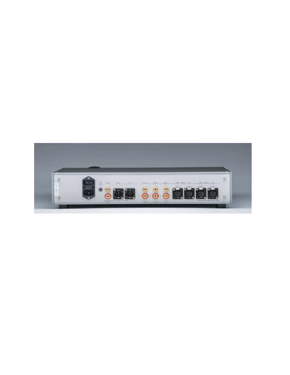
The preamplifi er’s voltage and current rating are indicated by affi xed tag on the rear
of the preamplifi er. The preamplifi er typically draws 30 watts during operation. Please
verify that the indicated voltage requirement of this preamplifi er is consistent with the
utility voltage at your location.
We have provided a standard IEC AC power cord that fi ts into the IEC 320 line
receptacle at the rear of the preamplifi er chassis. The preamplifi er is equipped for
operation with an earth ground provided by the users AC outlet. Do not defeat this
ground.
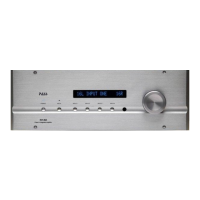
There are a total of fi ve inputs. Two of the fi ve inputs are balanced XLR only. The
other three inputs are single-ended only. There are two pairs of outputs, one pair
balanced, one pair single-ended.
On the XLR connectors, pin 1 is grounded, pin 2 is the positive signal, and pin 3 is
the negative signal. The RCA connector’s ground is in parallel with pin 1 of the XLR
outputs and the RCA hot is fed from an independent summing junction that maximizes
the X circuit benefi ts. The RCA, single-ended, outputs are buffered from the balanced
outputs. You may use both the single ended and balanced outputs at the same time.
On the XLR, pin 1 is ground, pin 2 is positive, and pin 3 is negative.