I
/1
SERVICE elect ra 3000 A
ANLEITUNG INSTRUCTION INSTRUCTION INSTRUCCION
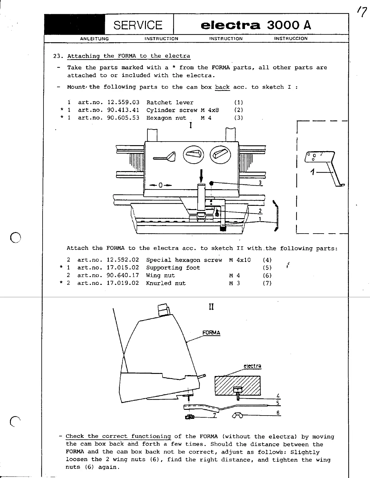
23. Attaching the FORMA to the electra
-Take the parts marked with a * from the FORMA parts, all other parts are
attached to or included with the electra.
-Moun~,the following parts to the cam box ~ acc. to sketch I :
1 art.no. 12.559.03 Ratchet lever (1)
* 1 art.no. 90.413.41 Cylinder screw M 4x8 (2)
* 1 art.no. 90.605.53 Hexa
gon nut M 4 (3)
I 1---
I
==~@@ I
~~-
J '1
-0- I
I
I
I
0 ---
Attach the FORMA to the electra acc. to sketch II with.the following parts:
2 art.no. 12.5S2.02 Special hexagon screw M 4x10 (4)
i
* 1 art.no. 17.015.02 Suppbrting foot (5) ~
2 art.no. 90.640.17 Wing nut M 4 (6)
* 2 art.no. 17.019.02 Knurled nut M 3 (7)
.~
II
~A
~lectra
~~~~~i-!!.
5
~::=::~::J=:::::=::::::::: -:
C 1- (J=<:J 6-
-Check the correct functioning of the FORMA (without the electra) by moving
the cam box back and forth a few times. Should the distance between the
FORMA and the cam box back not be correct, adjust as follow's: Slightly
loosen the 2 wing nuts (6), find the right distance, and tighten the wing
nuts (6) again.


 To Next Page
 Loading...