EasyManua.ls Logo

PAT DS 150 User Manual

PAT DS 150
31 pages
To Next Page IconTo Next Page
Page #1 background imageLoading...
Page #1 background image
User Manual IK 150 / 0031 e
© 1997 PAT GmbH · D-76275 Ettlingen · Hertzstr. 32 - 34 · ) ++49 (0) 7243 709-0 · FAX ++49 (0) 7243 709-222 · Email: pat.ettlingen@pat-gmbh.de 1
50 / 150 / 19_0031E.DOC / 19.03.1997 / Rev. C / rk.
The information in this document is subject to change without notice. PAT makes no warranty of any kind
with regard to this material, including, but not limeted to, the implied warranties of merchantability and fitness
for a particular purpose. PAT shall not be liable for errors contained herein or for identical or consequential
damages in connection with the furnishing, performance, or use of this manual. This document contains
proprietary information which is protected by copyright. All rights reserved. No part of this document may be
photocopied, reproduced, or translated to another language without the prior written consent of PAT.
USER MANUAL
IK 150 / 0031
doc. no. 50 150 19 0031 e
Question and Answer IconNeed help?

Do you have a question about the PAT DS 150 and is the answer not in the manual?

PAT DS 150 Specifications

General IconGeneral
BrandPAT
ModelDS 150
CategoryMeasuring Instruments
LanguageEnglish

Summary

1. General Information

2. Warnings

3. System Description

3.1 Operating Console

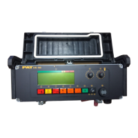
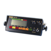
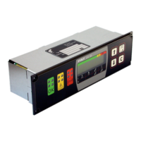
Describes the functions and components of the operator's console, including its terminal and display capabilities.

4. Control Identification

(1) LC Display

Details the Liquid Crystal Display, showing technical and operational data like radius, load, and boom parameters.

(2) Bargraph

Explains the bargraph indicator for crane rated capacity usage, divided into green, yellow, and red areas.

(3) Operating Code Switch

Explains the operating code switch for setting the LMI to the crane's configuration, stressing its importance.

(4) Reeving Switch

Describes the reeving switch for setting the number of falls (parts of line) used for the hook block.

(5) Anti-Two-Block Warning Light

Details the red warning light indicating an approaching two-blocking condition and the subsequent stopped crane movements.

(6) Prewarning Light

Explains the yellow prewarning light that activates when load is between 90-100% of crane rating.

(7) Overload Light / Alarm Switch

Describes the dual-purpose control for overload warning light and silencing the audible alarm.

(8) Tare Button

Explains the tare button for indicating net load by setting the display to zero before lifting.

Boom Angle Limits

(9) Setting of Boom Angle Limit: Maximum

Details how to store the actual boom angle as the maximum limit, indicated by a light and buzzer.

(10) Setting of Boom Angle Limit: Minimum

Details how to store the actual boom angle as the minimum limit, indicated by a light and buzzer.

(11) Enter Button "E"

(12) By-Pass Key Switch

(13) Audible Alarm

5. Pre-Operation Inspection and Calibration Verification

Operation

6. Service and Maintenance

7. Troubleshooting

Operating Errors

Describes malfunctions caused by range exceedings or operator errors, indicated by error codes E01-E05.

Pamphlet 1: Cut-off Values for Boom Cranes

Pamphlet 2: Important Notes for Crane Operators

Pamphlet 4: Electromagnetical Compatibility (EMC)

Pamphlet 5: Labour Protection During Repair

Pamphlet 6: Installation Instructions

Related product manuals