Do you have a question about the PAT DS150 and is the answer not in the manual?
Details document revision history and changes made.
Converts hydraulic pressure into an electrical analog voltage signal for system use.
Measures boom length and angle using a combination of two transducers.
Monitors load block position relative to boom head to prevent two-blocking.
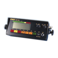
Displays geometrical data, load information, and provides alarm functions.
Digital inputs that program the system for specific lifting area configurations.
Illustrates the physical arrangement of system components on the crane.
Outlines the procedures for adjusting key system components for proper operation.
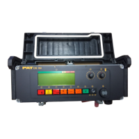
Describes the rugged, waterproof sheet steel housing of the central unit.
Details the main board, CPU, and EPROMs within the central unit.
Lists key components on the main board, including power supply and analog input.
Describes signals received from various transducers and their voltage ranges.
Explains the output signal for lever lockout and transducer voltage distribution.
The straight line measurement from boom pivot pin to boom point sheave pin.
The angle between the boom base section centerline and the horizontal plane.
Horizontal distance from rotation axis to hoist line center with rated load.
Load value from chart for specific crane configuration, boom, and angle.
The weight of the load being lifted plus all additional equipment.
Physical arrangement of crane for a particular operation.
Contact of lower load block with upper load block, boom point, or machinery.
Electrical signals varying proportionally to represented quantities.
Electrical signals of an on-and-off state representing operation quantity.
Schematic diagram detailing electrical connections of the system components.
List of part numbers and descriptions for the Central Unit DS150.
List of part numbers and descriptions for the Console DS150.
List of part numbers and descriptions for the Cable Reel LWG208.
Diagram showing the main board layout and test points for measurements.
Step-by-step guide for replacing EPROMs in the DS150 central units.
Procedure to adjust the zero point for pressure transducers.
Steps for calibrating the length and angle potentiometers and sensors.
Instructions for replacing the main board in the central unit.
Explanation of the circuit operation and its components.
Description of how the length measuring channel operates and its signals.
Details the operation and signal path of the piston side pressure channel.
Details the operation and signal path of the rod side pressure channel.
Explains the function and signal processing for the main boom angle sensor.
Explains the function and signal processing for the second angle sensor.
Provides an overview for diagnosing system problems and directing to specific flowcharts.
Step-by-step guide to troubleshoot lever lockout issues.
Guide to identify and resolve issues related to a broken or damaged length cable.
Steps to diagnose and fix a blank console display issue.
Procedure for diagnosing and resolving Anti-Two-Block system faults.
Guide to resolve errors related to data transfer between console and central unit.
Steps to identify and fix interference issues affecting the system.
Guide to diagnose and resolve incorrect angle readings.
Details causes and eliminations for range, zone, and length errors.
Details causes and eliminations for range, relay, and anti-two-block errors.
Details causes and eliminations for lower limit value errors in measurement channels.
Details causes and eliminations for voltage, program, and EPROM mismatch errors.
Details causes and eliminations for memory, A/D conversion, and EPROM errors.
Details causes and eliminations for data transmission and interference errors.
Procedure to measure the crane supply voltage at terminal X1.
Procedures to check main board power supply voltages against reference values.
Steps to measure voltage for boom length sensing.
Steps to measure voltage for boom angle sensing.
Procedures to measure voltage for pressure transducer zero points and references.
Reference table for signal voltages and nominal values for sensor channels.
Reference table for amplified signal voltages and test points for sensor channels.
| Output Signal | 4 - 20 mA |
|---|---|
| Protection Class | IP 65 |
| Operating Temperature | 50°C |
| Measurement Range | 0 |
| Storage Temperature | -20 °C |