Mechanical Description Of The System
1 MECHANICAL DESCRIPTION OF THE SYSTEM COMPONENTS
Pressure Transducer: The pressure transducer transforms hydraulic pressure into an electric analog
voltage signal. Two pressure transducers are connected, one to the rod side and one to the piston
side of the lift cylinder. The pressure transducer is connected to the central unit with a four-conductor,
double-shielded cable.
The power supply voltage is 5V.
The output signal is 0.00V under 0 pressure to -1.00V at max. pressure (4410psi)
The Length-Angle Transducer: The length-angle sensor (LWG) is a combination of two transducers
in one box, fitted at the base section of the boom. It measures the length and angle of the boom.
A reeling drum drives a potentiometer, which is the length transducer. Part of the length transducer is
the length cable on the drum, which is a two-conductor cable (screen and live). It is connected to the
anti-two-block switch at the boom head and to a slip ring body in the reel. The angle transducer is
fitted into a small box filled with oil. A pendulum drives the axle of the angle potentiometer.
The power supply voltage for both is -5.00V
The output signal for the length transducer is: -0.500V up to -4.500V
The output signal for the angle transducer is: -1.875V up to -3.125V
Anti-Two-Block Switch: The anti-two-block switch monitors the load block and its relationship with
the head of the boom. In working condition, the switch is closed. When the hook block strikes the
weight, the circuit opens, disengaging a relay output to the lockout solenoid valves, where applicable.
To check the cable for damage, (short circuit to ground) there is a 4.7k resistor between ground and
the contact of the switch. The weight at the anti-two-block switch keeps the switch closed until the
hook block strikes it.
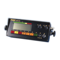
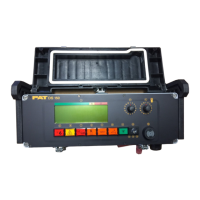
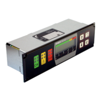
Console: The console displays the geometrical information such as length and angle of main boom,
working radius and head height of the boom. It also displays the actual load and the maximum load
permitted by load chart. Furthermore, it has an alarm horn and a warning light for overload, and a pre-
warning light. The analog instrument shows a percentage of the total permissible moment. The
console has a switch for the operating modes (duty-selection switch for crane configurations) and a
switch for the Reeving of the hook block. It also has a warning light for anti-two-block conditions and
an override switch for overload or anti-two block condition.
Duty Selection Switches (Digital Inputs): The system has to be programmed for the lifting area
configuration. The crane is going to be worked in (e.g. main boom) on outriggers over front, or rear, or
over the side for 360 degrees. For obtaining this information from the crane, micro switches are
installed in the electrical swivel that tells the system the exact location of the boom. Micro switches
are also located on the counterweight which tells the system if the counterweight is installed or not,
where applicable.