accessed through the pie eyes on the port starboard side of the transom. In the open
position, these ball valves will allow water to flow freely
from the cockpit, thus making the boat “self-bailing”. When
closed, no water will be allowed to travel to or from the
cockpit.
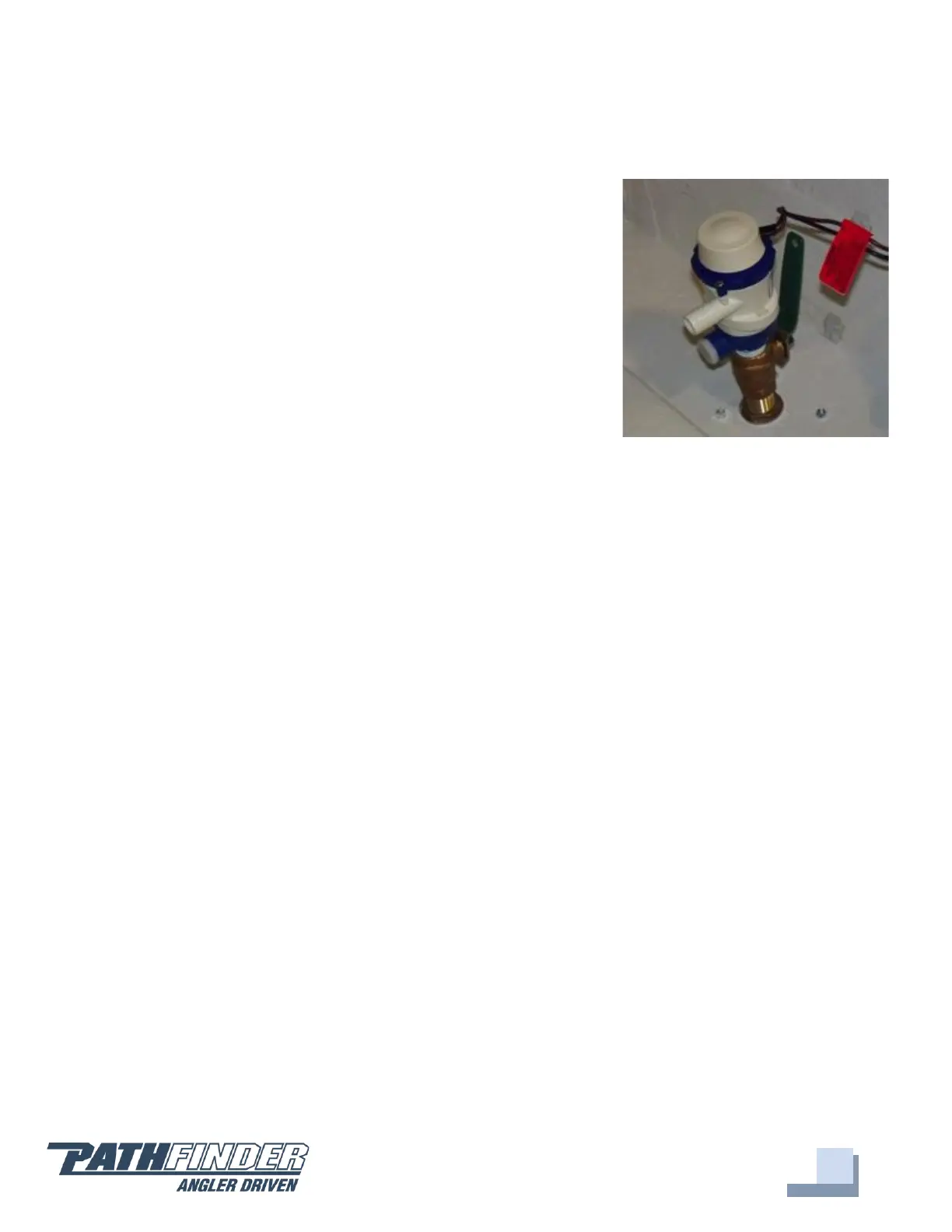
2005 Livewell Pump Assembly
The livewell pump assembly is composed of a scoop
strainer mounted to the bottom of the hull, a thru hull
fitting, ball valve assembly, and the pump. As you can see,
the ball valve assembly is in the “OPEN” position. This is
the correct position for the operation of the livewell.
Trolling Motor Wiring
Trolling Motor/Wiring System
Your Pathfinder 2005 TRS comes standard with a 24V trolling motor wiring system. A
trolling motor mounting plate was built into the bow of your Pathfinder during the
manufacturing process. To attach a trolling motor, please go to your nearest Pathfinder
dealer. All trolling motors should be attached by drilling through the mounting plate
with a 13/64” drill bit and 1/4” tap and using 1/4” #20 machine screws. The plate is
designed to accommodate the mounting patterns of all trolling motor brands on the
market currently. See page 25 for optional trolling motor system with battery charger
and wire routing.
Battery Switch and Breaker Panel
Battery Switch and Breaker Panel
The battery switch and main breaker panel is located in the glove box. The top 50-amp
breaker is the main power for the boat, which feeds the switch panel on the helm and its
associated accessories along with engine power. The 7-amp breaker below that is for the
bilge and the remaining two 15-amp breakers are for adding additional accessories.
Between each breaker and its label there is a small LED light which will be illuminated if
that breaker and its corresponding system is receiving power. When the battery switch is
on the “off” position, only the light for the bilge should be on, as the bilge pump and
float switch are wired directly to the batteries so that they remain operational at all