4
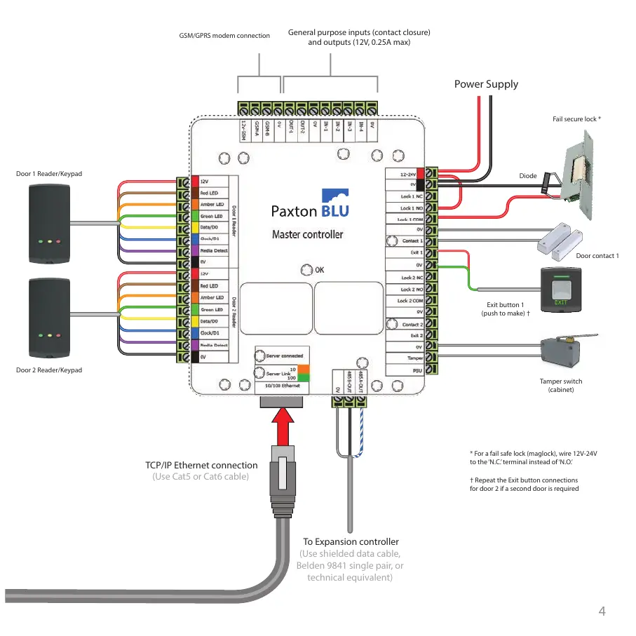
Power Supply
General purpose inputs (contact closure)
and outputs (12V, 0.25A max)
GSM/GPRS modem connection
Exit button 1
(push to make) †
Door contact 1
Fail secure lock *
* For a fail safe lock (maglock), wire 12V-24V
to the ‘N.C.’ terminal instead of ‘N.O.’
† Repeat the Exit button connections
for door 2 if a second door is required
Diode
Door 1 Reader/Keypad
Door 2 Reader/Keypad
To Expansion controller
(Use shielded data cable,
Belden 9841 single pair, or
technical equivalent)
TCP/IP Ethernet connection
(Use Cat5 or Cat6 cable)
Tamper switch
(cabinet)