5
Power Supply
General purpose inputs (contact closure)
and outputs (12V, 0.25A max)
GSM/GPRS modem connection
Exit button 1
(push to make) †
Door contact 1
Fail secure lock *
* For a fail safe lock (maglock), wire 12V-24V
to the ‘N.C.’ terminal instead of ‘N.O.’
† Repeat the Exit button connections
for door 2 if a second door is required
Diode
Door 1 Reader/Keypad
Door 2 Reader/Keypad
To Expansion controller
(Use shielded data cable,
Belden 9841 single pair, or
technical equivalent)
TCP/IP Ethernet connection
(Use Cat5 or Cat6 cable)
Tamper switch
(cabinet)
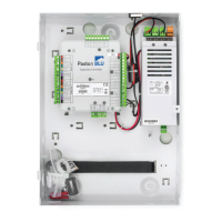
Overview
LED diagnostics
The Paxton BLU Master Controller connects to the cloud based server through a TCP/IP Ethernet port or through the optional GSM/GPRS modem.
If you are running a DHCP server on your network then you do not need to congure the communication settings as a static IP address is not
required. The section below (Conguring the Paxton BLU Control Master unit) explains how to congure the unit if you do not have a DHCP server.
The GSM/GPRS modem does not require any user conguration.
To add additional doors to the site, up to a maximum of 50, you should purchase the Paxton BLU Expansion Controllers. These connect via the
self-terminating RS485 bus connection, no additional termination is required. Larger sites are accommodated by using multiple master units that
can be logically grouped in the software.
Please be aware that if you dont have an Ethernet connnection then by default the unit will attempt to connect through the GSM network.
This would require the purchase of a Paxton BLU Modem and activation license.
• Contact 1 (Orange) Door 1 contact closed
• Contact 2 (Orange) Door 2 contact closed
• RS485-OUT (Orange) Unit receiving data
• OK (Green) Flashing on and o to indicate trying to connect (0.5 secs)
• OK (Green) Flashing to indicate unit is connected(fast ash once per second)
• OK (Green) On for 3 secs then ashing, see diagnostics below.
• Server connected (Orange) The TCP/IP interface is connected
• Server link (Green/Orange) 10/100 Mbits/sec
• IN-1 to IN-4 (Orange) Activity on inputs IN-1 to IN-4
LED diagnostics - OK LED on for 3 seconds then 0.5 second ash indicates -
• Ok - 1 Flash Error 1 Internal controller fault (reset failed) contact Paxton Inc
• Ok - 2 ashes Error 2 Not currently used
• Ok - 3 ashes Error 3 Not currently used
• Ok - 4 ashes Error 4 GSM service connection cannot be found
• Ok - 5 ashes Error 5 GSM modem not connected
• Ok - 6 ashes Error 6 Not currently used
 Loading...