441A152 PEAK METER 8
Manual 23528 Rev. A
ECN 50523
Appendix A: RS-232 Control
For RS-232 communication, the port settings should be as follows:
RS-232, DCE interface, XON/XOFF flow control,
Asynchronous protocol
The message format is as follows:
Destination
ID
(Rack/Slot)
STX (0x02) - marks the start of a new message.
16 bits - rack code (0-3 ASCII) followed by slot address (0-9 ASCII). Messages meant
for the master will have "MM" in this field.
Contains the command followed by any associated data. See below for command
structure, and command set for examples.
ETX (0x03) - marks the end of the message.
16 bits - the ASCII hex of the 8-bit sum, ignoring overflows, of all bytes in the message
including SOT and ETX bytes.
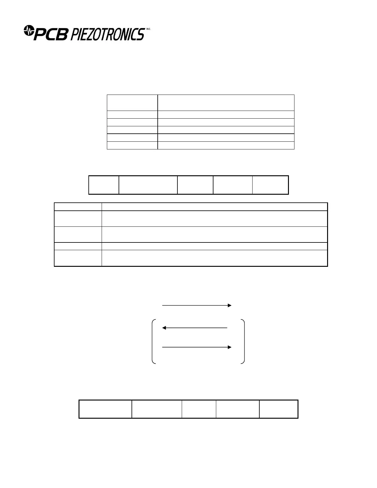
All messages sent to the rack will receive a response. A typical command transaction is shown below.
Host Rack
Command
ACK [data]
NACK [reason]
The ACK/NAK field conveys information concerning the delivery of messages. The results of command
operations are contained in the data field of an ACK message. NAK reason bytes are defined below.
The format of an ACK message.