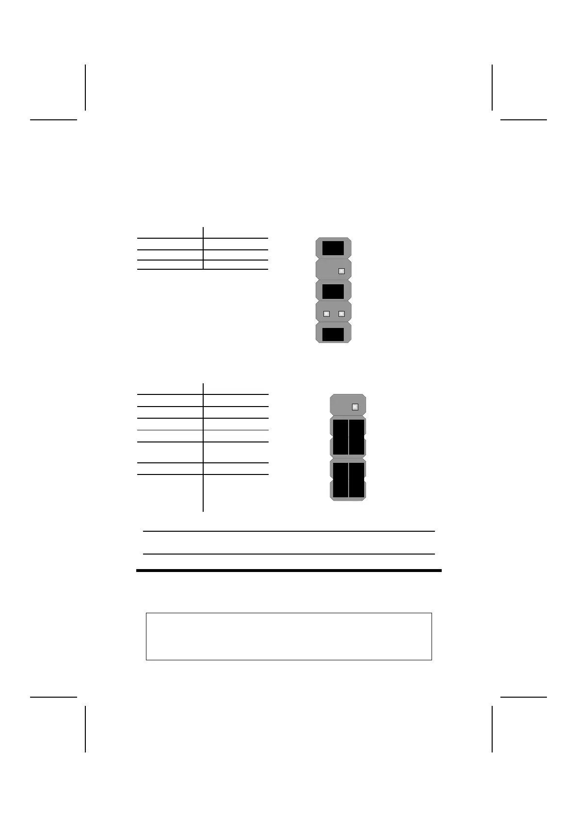
The Panel Connectors
The panel connector (PANEL1 and PANEL2) provides a standard set of switch
and LED connectors commonly found on ATX or micro-ATX cases. Refer to
the table below for information:
PANEL1
Device Pins
Line Out (L) 9, 10
Line Out (R) 5, 6
MIC In 1, 2
MIC In
(Pins 1, 2)
2 1
Line Out(R)
(Pins 5, 6)
10 9
Line Out(L)
(Pin 9,10)
PANEL2
Device Pins
Empty 10
N/C 9
Power ON/OFF 6, 8
Reset Switch 5, 7
Green LED
Indicator
2, 4
HDD LED +1, -3
HDD LED
(Pins 1, 3)
2 1
Reset Switc
(Pins 5, 7)
Power Switch
(Pins 6, 8)
Green LED
(Pins 2, 4)
Empty
(Pin 10)
10 9
N/C
(Pin 9)
Note: The plus sign (+) indicates a pin which must be connected to a positive
voltage.
I
I
n
n
s
s
t
t
a
a
l
l
l
l
i
i
n
n
g
g
H
H
a
a
r
r
d
d
w
w
a
a
r
r
e
e
Installing the Processor
Caution: When installing a CPU heatsink and cooling fan make sure that
you DO NOT scratch the mainboard or any of the surface-mount resistors
with the clip of the cooling fan. If the clip of the cooling fan scrapes
across the mainboard, you may cause serious damage to the mainboard
or its components.
10
 Loading...