Section 1
SETTI NG UP I NSTRUCTI ONS
WARNI NG
: ALWAYS ENSURE THAT THE POWER I S DI SCONNECTED BEFORE REMOVI NG
COVER.
a. SETTI NG UP: Load Cells.
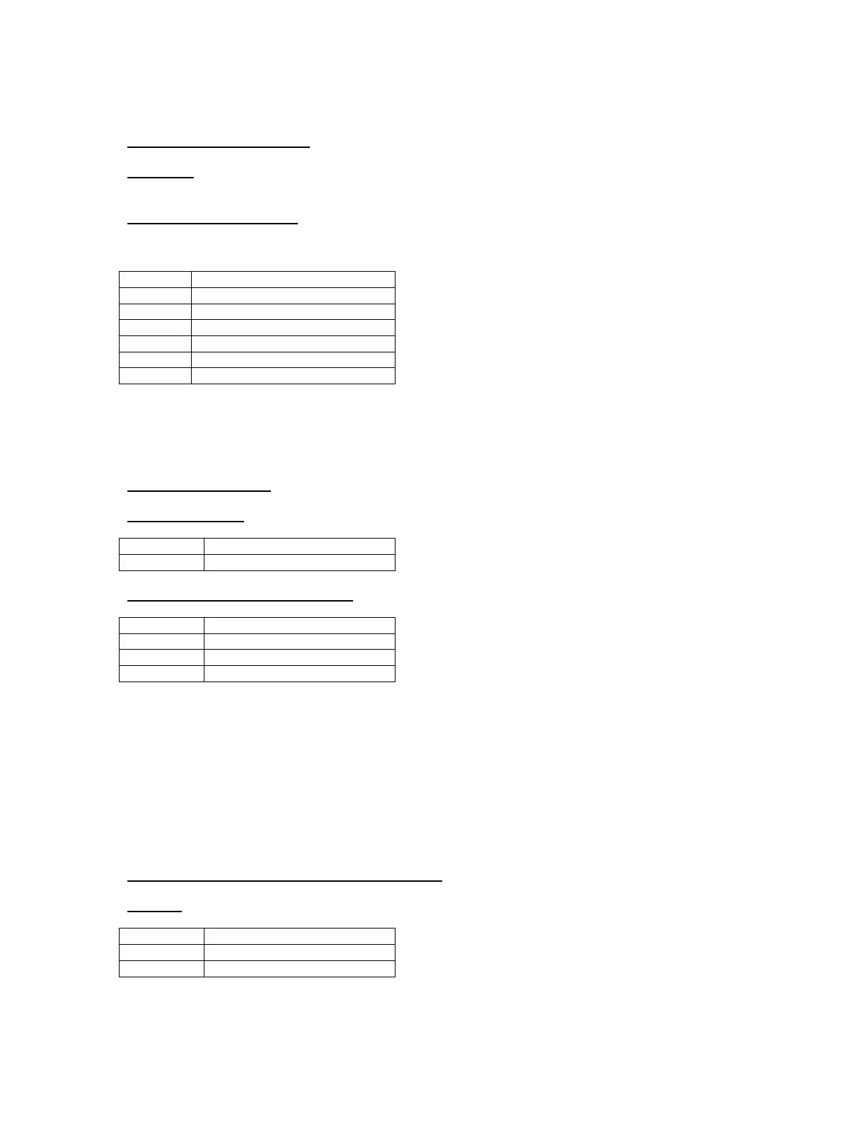
The load cell connector is a seven way screw terminal connector:
NOTE REGARDI NG SENSE TERMI NATI ON
The sense inputs are for use with six wire load cells that have remote voltage sensing in order to
compensate for resistive loss within the cable run. If a load cell is used without this feature then connect the
positive excitation to positive sense and negative excitation to negative sense.
b. SETTI NG UP: Power
i. DC Applicat ions:
ii DC Applicat ions: Bat tery Versions
Suitable Charging Adaptor: approx 12vdc@300mA minimum
Correct Procedure to charge unit:
1. With the adaptor AND Junior switched OFF plug the adaptor jack into the unit.
2. Switch on the Adaptor and allow approx 12 hours to fully charge (from a fully discharged state). You can
use the unit whilst in charging mode.
3. Once the charge cycle is complete press and hold the ZERO key to switch off the Junior and sw it ch OFF
the adaptor via the mains outlet.
4. Disconnect the Adaptor jack from the Junior and use normally until the Battery Low indicator is indicated
then complete cycle.
iii. AC Applications: ( 110-240VAC Auto Selection)
DANGER
: WARNING LI VE TERMINALS EXPOSED WHEN REAR COVER REMOVED
Please note: AC power supply automatically senses the mains supply voltage.
 Loading...