15 16
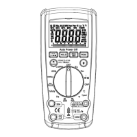
Meter Functions – Frequency(Hz)
Select the “Hz” Frequency
function with the function dial.
Insert:
Black lead in COM terminal.
Red lead in V-
-RPM terminal.
Connect the Black test probe to
ground.
Connect the Red test probe to the
“signal out” wire of the sensor to be
tested.
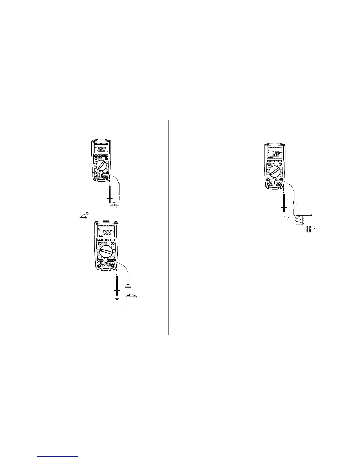
Meter Functions-Dwell ( )
Select the “
DWELL” function
with the rotary switch.
Insert:
Black lead in
COM terminal.
Red lead in V-
-Hz-RPM
terminal.
Connect the Black test probe to
ground.
Connect the Red test probe to the
wire that connects to the breaker
points (see illustration).
Meter Functions - Duty Cycle (%)
Select the “%
Duty” Cycle
function with the function dial.
Insert:
Black lead in
COM terminal.
Red lead in V-
-%-RPM terminal.
Connect the Black test probe to
ground.
Connect the Red test probe to the
signal wire circuit.
The illustration for a mixture control
solenoid is shown with the metering
rod in the closed position. The meter
will display the percentage of time the
plunger is in the closed position. (low
duty cycle) during one duty cycle.
Meter Functions - ms-PULSE (Pulse Width) & ms-
PERIOD (Period)
Pulse Width is the length of time an actuator is energized. For example,
fuel injectors are activated by an electronic pulse from the Engine
Control Module (ECM).
This pulse generates a magnetic field that pulls the injectors nozzle
¦¸
Auto Power Off
4
2
Black-
Red +
To breaker
points
¦¸
Auto Power Off
4
2
Black-
Red +
"Signal Out"
Side
Ground
Side
"Vol ta g e I n"
Side
¦¸
Auto Power Off
4
2
Black-
Red +
Mixture
Control
Shown
Mixture
Control
Shown
 Loading...