Symbol
-H
Hz,
kHz, MHz
le
1.
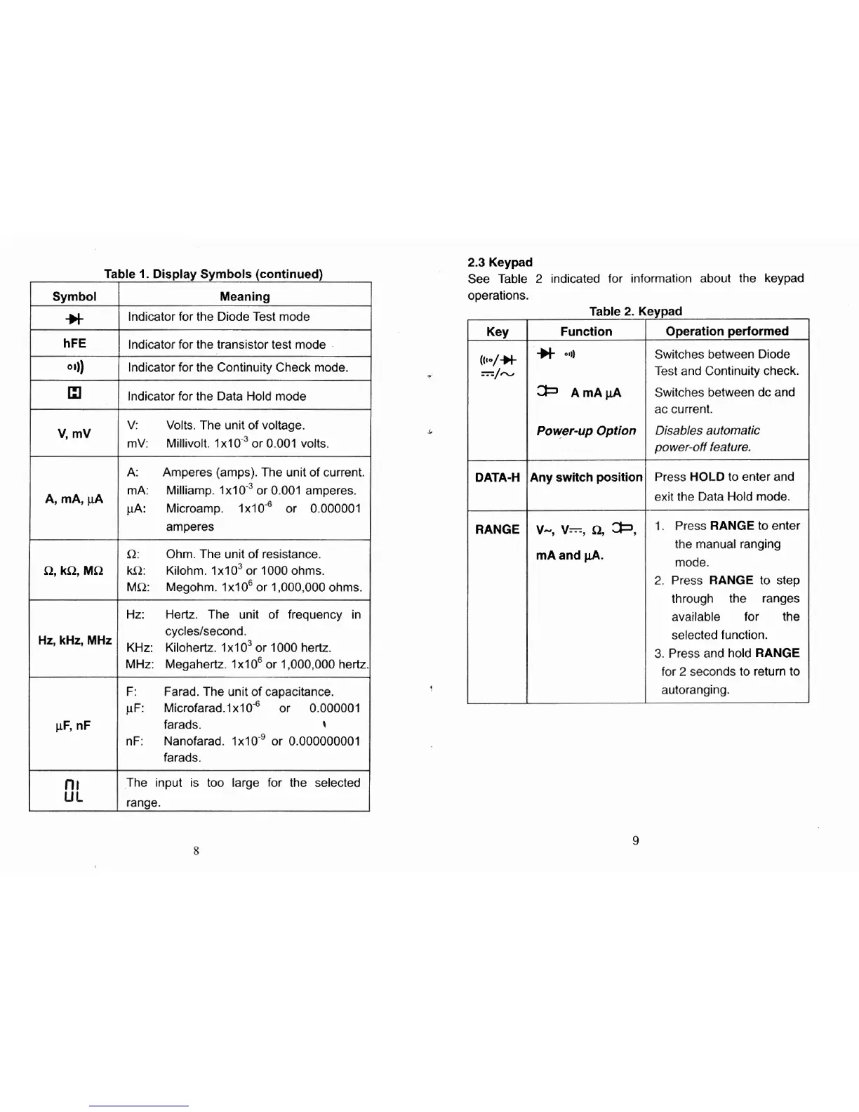
Display Symbols (continued)
Meaning
Indicator for the Diode Test mode
lndicator for the transistor test mode
lndicator for the Continuity Check mode.
lndicator for the Data Hold mode
V:
Volts. The unit of voltage.
mV: Millivolt. 1x10~~ or 0.001 volts.
A:
Amperes (amps). The unit of current.
mA: Milliamp. 1x10.~ or 0.001 amperes.
pA:
Microamp. 1x10.~ or 0.000001
amperes
R: Ohm. The unit of resistance.
kR: Kilohm. 1x10~ or 1000 ohms.
MR:
Megohm.
1x10~ or 1,000,000 ohms.
Hz: Hertz. The unit of frequency in
cycleslsecond.
KHz: Kilohertz.
lxlo3 or 1000 hertz.
MHz: Megahertz.
1x10~ or 1,000,000 hertz
F:
Farad. The unit of capacitance.
vF: ~icrofarad.1~10-6 or 0.000001
farads.
t
nF:
Nanofarad. 1x10'' or 0.000000001
farads.
The input is too large for the selected
ranae.
2.3
Keypad
See Table
2
indicated for information about the keypad
operations.
Switches between Diode
Test and Continuity check.
ac current.
Power-up
Option
Disables automatic
power-off feature.
I
DATA-H Any
switch
position
RANGE
V-,
V=,
R,
*,
mA and
pA.
Press HOLD to enter and
exit the Data Hold mode.
1.
Press RANGE to enter
the manual ranging
mode.
2.
Press RANGE to step
through the ranges
available for the
selected function.
3.
Press and hold RANGE
for
2
seconds to return to
autoranging.