KITE CEILING FAN LED
Installation Manual
REV 2023 0511
SPECIFICATIONS AND DETAILS ARE SUBJECT TO CHANGE WITHOUT NOTIFICATION. CONTACT PEACOCK FAN COMPANY FOR UP TO DATE DETAILS.
PEACOCK FAN COMPANY • PEACOCKFAN.COM
SAVE THESE INSTRUCTIONS
4
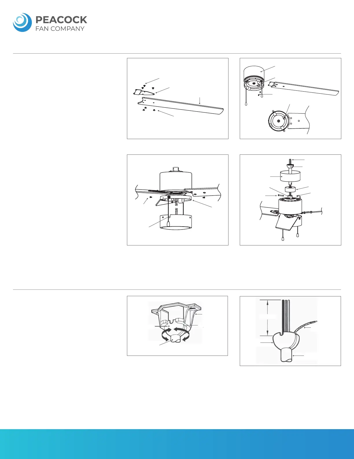
FAN ASSEMBLY
HANGING THE FAN
A) Align the screw holes in blade arm with fan blade.
Locate blade screws and nuts. Fasten with 3 sets for
each blade. Make sure the nuts are facing down and
screws facing up. Repeat for the remaining blades.
(Figure 6)
B) Rotate the motor so a screw hole can be seen
through the opening in the switch box. Place the
blade arm between the motor and switch box. Align
the holes in blade arm and motor. Secure with 2 motor
screws for each blade arm. Rotate the motor and
repeat for the remaining blade arms. (Figure 7)
C) Loosen and save the 3 screws on the switch box.
Locate light kit. Connect wire sockets from light kit
and motor. Place light kit onto switch box. Align slots
in light kit with switches on switch box. Secure with 3
screws loosened previously. (Figure 8)
D) Loosen joint screw halfway to clear the way for
downrod. Take out and save the safety pin on the
downrod. Place the canopy and then joint cover onto
the downrod. Thread power wires from the motor
through the downrod. Insert downrod into the motor
joint. Align holes and insert safety pin and clip. Fasten
the joint screw. (Figure 9)
A) Insert the support rod in the side of the mounting
bracket. Notice the ball hanger is grooved on one side
(figure 10). This keyway fits over the small keyway pin
on the inside of the mounting bracket and keeps ceil-
ing fan from spinning on the mounting bracket.
B) Turn the support rod left and right slightly o make
sure it is seated on the bracket with the keyway.
C) Trim the lead wires, leaving about 6 inches of each
wire extending from the support rod. (Figure 11)
FIGURE 6 FIGURE 7
Blade Screws
Blade Arm
Fan Blade
Blade Nuts
Motor Assembly
Switch Box
Motor Screws
Switch Box Opening
FIGURE 8
Switch
Box
Light Kit
Slot
Switch Box
Screws
FIGURE 9
Canopy
Motor Joint
Safety Pin
Power Wires
Downrod
Joint Cover
Joint Screws
Ball Hanger
Ball
Hanger
Support Rod
Keyway Pin
Mounting
Bracket
Ground Wire
6"
Support Rod
FIGURE 10
FIGURE 11