De
termine which are the positive (+) and negative (-) wires for the reverse lights on the vehicle. You 5.
ca
n use either the right- or left-side reverse light wires. For help locating the vehicle’s reverse light
circuit, contact your vehicle’s manufacturer for vehicle-specic wiring diagrams.
Remove the vehicle’s negative (-) battery cable. 6.
2
1
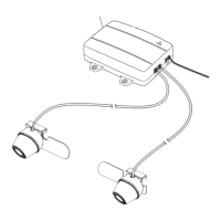
Legend
1.
Wire from Vehicle
2.
Wire from Controller
Once the proper wires for the reverse lights have been determined, the controller wires must 7.
be
spliced into the vehicle wires using the supplied wire connectors. If you choose to wire the
controller using a dierent method, you must be knowledgeable in 12-volt DC electrical practices.
The red positive (+) wire from the controller splices into the positive (+) wire from the reverse lights 8.
and the black negative (-) wir
e from the controller splices into the negative (-) wire from the reverse
lights.
Position the connector around the vehicle wire you are splicing into.9.
Slide the appropriate wir
e from the controller into the connector.10.
Cr
imp the metal clamp using a pliers to ensure a good connection and then close the lock of the 11.
wire connector
. Do this for both the positive (+) and negative (-) wires from the reverse light.
Decide on a suitable mounting position for the controller and mount it using the screws from the 12.
ha
rdware bag or the adhesive-backed mounting pad. It must be mounted in an area where the
wires from the sensors can be plugged into it.
Reconnect the vehicle’s negative (-) battery cable.13.
Plug the controller po
wer wire plug into the controller.14.
D
epending on your vehicle type, it may be necessary to drill a hole to route the
sensor wires. Before you drill a hole you MUST CHECK WHAT IS BEHIND THE DRILLING
LOCATION. If there are any vehicle components, like electrical parts or fuel system
components, behind the drilling location, you must take precaution not to damage them.
Route the wires from the sensors to the controller. Some vehicles may have a hole to route the 15.
sensor wires thr
ough; for example, the hole for the wires for the license plate light.
If you need to drill holes, use a half inch (1/216.
" [
13 mm]) drill to drill the holes. Install the plastic
grommets in the holes. You must use the grommets to prevent the edge of the hole from damaging
the sensor wires.
Insert the sensor wires through the grommets and route them to the controller.17.
Plug the sensor wires into the contr
oller and secure the wires with wire ties if needed.18.
Attach the r
eceiver mounting arm to the receiver using the mounting arm screw and a nut. 19.
Fi
nd a suitable mounting position inside the vehicle for the receiver where it can be easily seen 20.
and heard, but not in a position wher
e it can obstruct your vision when driving.
Use the adhesive-backed mounting pad to secure it to the desired mounting position. The angle of 21.
the receiv
er can be adjusted by loosening the screw on the back and tilting the receiver.
The receiver can be powered using the receiver cigarette lighter/accesory socket power cord or 22.
the receiv
er power cord. If you are going to hard wire it using the receiver power cord, you must
nd a switched positive (+) and negative (-) wire from the vehicle wire harness.
Plug the receiver power cord into the power port of the receiver.23.
If
using the receiver cigarette lighter/accesory socket power cord, plug it into a 12-volt DC power 24.
port.
R
oute and secure all wires as needed.25.
When using the sy
stem for the rst time, the controller and receiver must recognize each other.26.
Tu
rn the power switch for the receiver to the ON position. The green power LED on the receiver 27.
will light.
Wi
th park brake still applied, turn the vehicle ignition switch to the ON position only. Do not start 28.
the vehicle
.
Shift the vehicle to reverse to power the controller.29.
 Loading...