Description
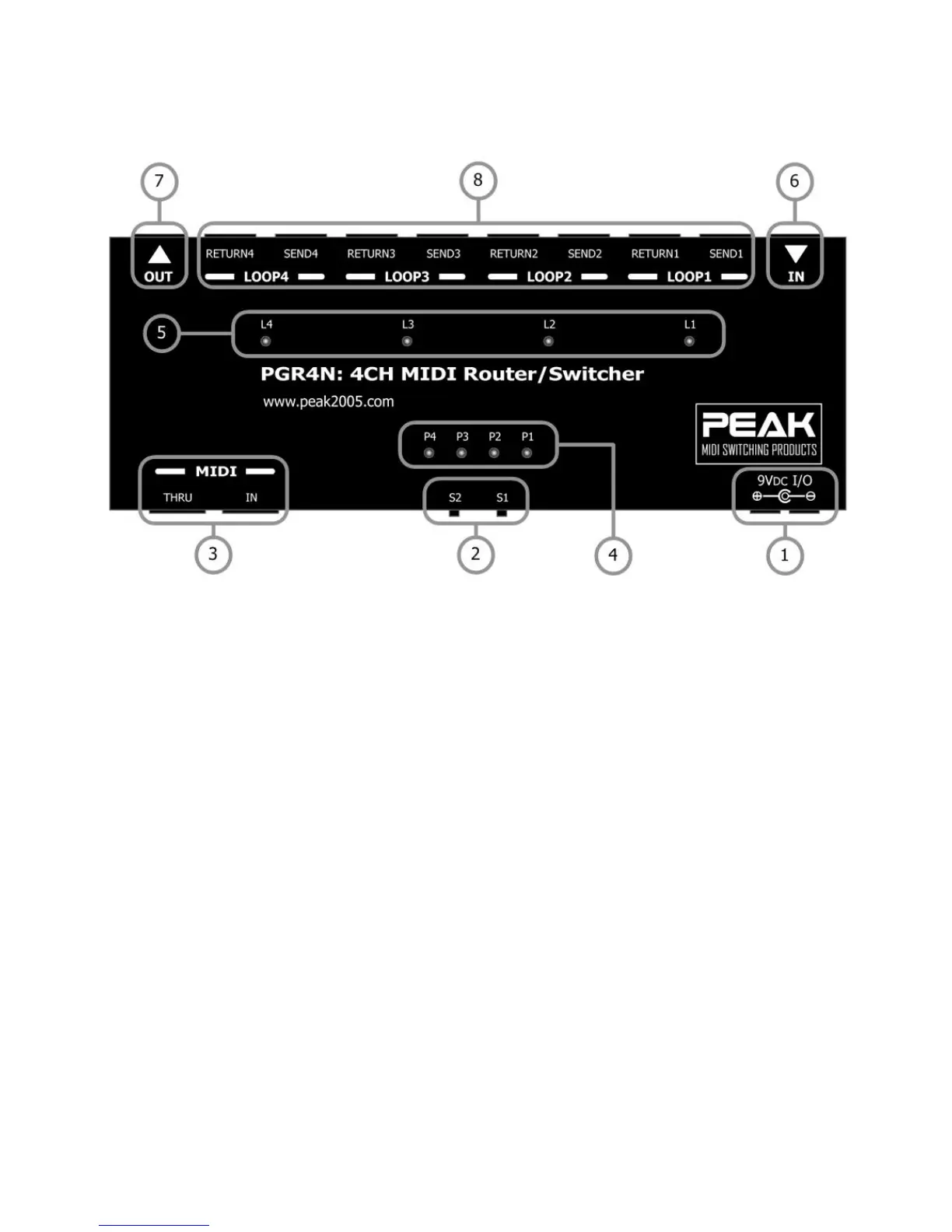
(1) POWER In/Out: 9V/DC, 250mA with double terminals for linking to other devices.
** We recommend the Boss PSA-100/110/120/220/230 or 240 depending on your
local AC supply voltage **
(2) S1, S2: These switches are used to configure the PGR4N.(see details in the next section)
(3) MIDI IN-THRU: * MIDI IN: This is a 7-pin DIN jack for MIDI cables. It allows the PGR4N to receive
commands from an external MIDI device. You can use standard MIDI cable both 5
pins and 7 pins to connect to the MIDI IN port. The PGR4N supports phantom
power over pin6 and pin7 of the standard 7 pins MIDI cable.
* MIDI THRU: This is a 5-pin DIN jack for MIDI cables. It passes MIDI commands
received by the MIDI IN jack to other MIDI devices.
(4) P1, P2, P3, P4: These 4 LED's display Mode and Preset status.
(5) L1, L2, L3, L4: These 4 LED's display loop ON/OFF status. When the LED is on the loop is active.
(6) IN: This is standard 1/4” mono jack. This accepts an audio signal from an external
source such as a guitar.
(7) OUT: This is a standard 1/4” mono jack that routes the audio signal from the PGR4N
loops to an external device, such as a guitar amplifier.
(8) LOOP1 – LOOP4: These are standard 1/4” mono jacks that provide or control Loop#1 to Loop#4.
* SEND: Provides a switchable (muting) output signal to the input of an external
device/effect.
*RETURN: This accepts an audio signal from an external device/effect.