Install the nuts with the arrow pointing towards the device as
shown in the figures.
The components labeled with X in Fig. 6 and 7 are not used for
the relative application.
5. Route supply wires through the conduit fitting into the wiring
chamber.
6. Connect the supply ground wires to the ground lug in the
wiring compartment.
NOTICE: The safety earth ground connection is marked at its
terminal using the (fig. 8, 9, 10).
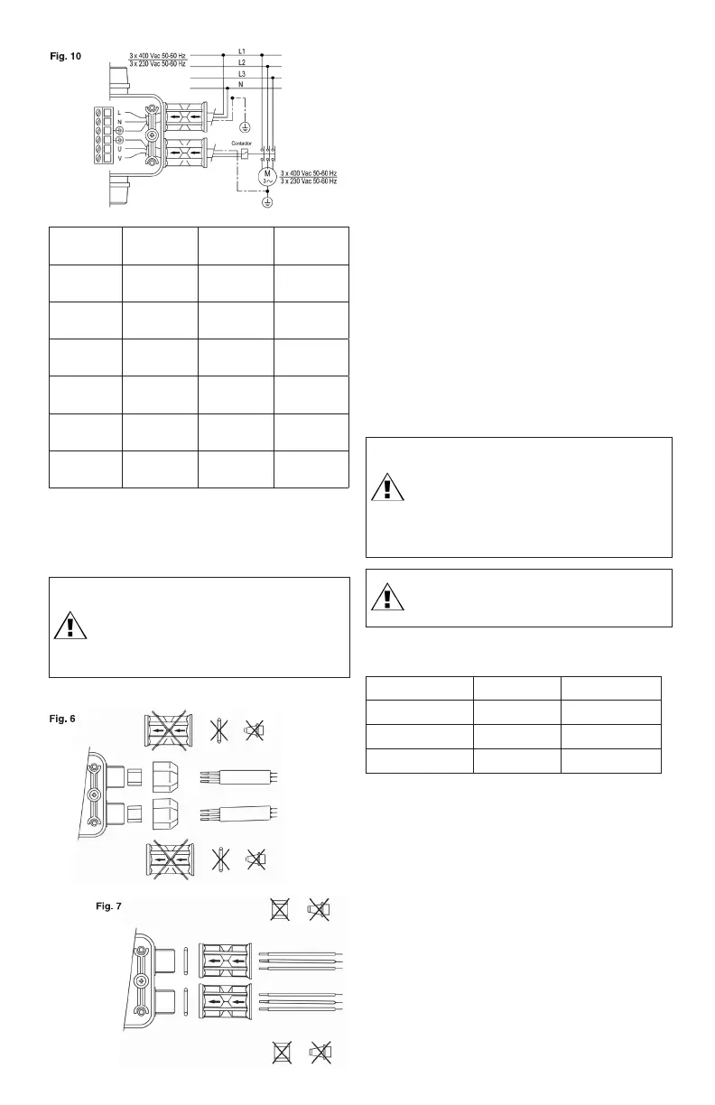
7. Connect the supply wires to the screw terminal marked L
and N (fig. 8, 9, 10). Use only copper wires rated for at least
140°F (60°C). Lead wire terminals should be tightened to a
torque of 4 in-lbs (0.5 Nm).
8. Connect the motor wires to the screw terminal marked U
and V (fig. 8, 9, 10). Use only copper wires rated for at least
140°F (60°C). Lead wire terminals should be tightened to a
torque of 4 in-lbs (0.5 Nm).
9. Replace the cover and tighten the six screws. For proper
sealing, the screws should be tightened to a torque of 13
in-lbs (1.5 Nm).
6. STARTING
WARNING: Failure to follow this instruction may result in
heating of water, personal injury, pump damage, and/or
property damage.
The device can be installed directly on the pump or
between the pump and the first tap with the flow
direction arrow facing upwards. Taps must not be
installed between the pump and the device (fig. 1).
WARNING: If the pressure generated by the pump
exceeds 174 psi (12 bar), apply a reducer between the
pump and the device.
Make all the electrical connections, check that the pump is
correctly primed, open a tap, and energize.
MAINS
VOLTAGE
MOTOR
VOLTAGE
MOTOR
POWER
ELECTRICAL
DIAGRAM
Single-phase
115 V
Single-phase
115 V
Not more
than 1.1
See figure 8
Single-phase
115 V
Single-phase
115 V
Over 1.1 See figure 9
Three-phase
230 V
Three-phase
230 V
- See figure 10
Single-phase
230 V
Single-phase
230 V
Not more
than 2.2
See figure 8
Single-phase
230 V
Single-phase
230 V
Over 2.2 See figure 9
Three-phase
400 V
Three-phase
400 V
- See figure 10
4. When mounting in wet environments, liquid-tight cables or
conduit fittings are required (not supplied) to ensure that the
enclosure maintains a water-tight, Type 4 rating. Install the
liquid tight cables or conduit fitting into the conduit nuts in
front of the power supply and motor connectors (fig. 6, 7).
WARNING: Liquid-tight cables or conduit and fittings
must be used to maintain a Type 4 rating (fig. 6, 7).
If you use a liquid-tight cable (fig. 6), tighten the nuts
to a torque of 106 in-lbs (13 Nm). If you use conduit
fittings (fig. 7), tighten the nuts to a torque of 106
in-lbs (13 Nm).
The nuts must compress the Oring to the body of the device.
7. CONTROL PANEL
The green Power on LED will light up on the control panel and
the pump will start (yellow Pump on LED on) and keep running
for several seconds to start up the system.
If this time is insufficient, the device will stop the pump (red
Failure LED blinking).
Keep the Restart button pushed in until the red Failure LED turns
off and the water comes out of the opened tap.
When the tap is closed the pump will stop after a few seconds
(yellow Pump on LED turns off).
From now on the device will turn the pump on and off
depending on the opening and closing of the tap.
GREEN LED ON Power on Device energized
YELLOW LED ON Pump on Pump running
RED LED BLINKING Failure Water shortage
BUTTON Restart Reset after failure
 Loading...