Do you have a question about the Peavey PV35XO and is the answer not in the manual?
Alerts user to dangerous voltage within the product enclosure.
Alerts user to important operating and maintenance instructions.
Warns against opening the enclosure to reduce electric shock risk.
Advises against exposing the apparatus to rain or moisture.
Provides instructions on product usage, installation, and environment.
Details servicing requirements, grounding, and noise exposure limits.
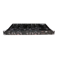
Optimizes channel I gain between mixer and power amps.
Indicates signal clipping, which may cause distortion.
Sets crossover points for lows and low-mids for channel 1.
Multiplies crossover selector range for lows/low-mids by 10.
Sets crossover points for mids and highs for channel 1.
Multiplies crossover selector range for mids/highs by 10.
Controls output level for channel I low frequency signal.
Controls output level for channel 1 mid frequency signal.
Controls output level for channel 1 high frequency signal.
Combines sub frequencies from both channels into a single output.
Mutes low and low-mid outputs in mono mode.
Selects mono 5-way operation; red LED indicates mono mode.
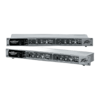
Standard IEC power connector with integrated fuse holder for mono operation.
Specifies the operational bandwidth and frequency response range.
Details Total Harmonic Distortion and signal-to-noise performance.
Identifies the filter type and slope as 24 dB/Octave.
Outlines the frequency range for variable state controls in stereo and mono modes.
| Type | Stereo 2-Way/Mono 3-Way |
|---|---|
| Frequency Range | 20 Hz - 20 kHz |
| Filter Type | Linkwitz-Riley |
| Slope | 24 dB/octave |
| Maximum Input Level | +22 dBu |
| Maximum Output Level | +22 dBu |
| Input Connectors | XLR |
| Output Connectors | XLR |
| Power Supply | 100-240V AC, 50/60 Hz |
| Input Impedance | 20 kΩ balanced, 10 kΩ unbalanced |