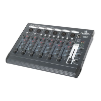
CHANNEL FUNCTIONS:
The Following applies to Channels 1-6:
1. MIC INPUT: XLR balanced low impedance channel input
optimized for a microphone or other low impedance source.
Pin 2 is the positive input. Because of the wide range of gain
adjustment, signal levels up to +5 dBu (1.3 V RMS) can be
accommodated.
2. MIC GAIN: Varies the input gain to allow for a wide dynamic
range. It affects both the line and mic inputs on Channels 1 and
2. Channels 3-6 have separate gain controls for Line and Mic
inputs (see #1 and 10). Proper adjustment of the input gain
through use of the LED level meter will maximize the signal-to-
noise ratio. Application note #9 on page 8 explains this simple
method in detail.
3. PAN: Sets the channelÕs position in the L/R fields. For stereo
channels (3, 4, 5 and 6), the Pan also acts as a balance control.
As one field is increased the other is decreased. For instance,
increasing the left signal (turning the knob counter-clockwise)
will result in a decrease of the right signal.
4. HI EQ: A shelving type of active tone control that varies the
treble frequency levels +/-15 dB at 10 kHz. It is designed to
remove noise or to add brilliance to the signal, depending on
the quality of the source.
5. LOW EQ: A shelving type of active tone control that varies
the bass frequency levels +/-15 dB at 70 Hz. It will add depth to
thin signals, or clean up muddy ones.
6. MON: Adjusts the level of the channel signal (pre-EQ) that is
added to the monitor mix. This is a mono mix of the left and
right signals in the stereo channels. The center detent is the
unity gain position.
7. EFX: Adjusts the level of the channel signal (post-EQ) that is
added to the effects bus. This is a mono mix of the left and right
signals.
8. FADER: Channel output level control. The level of the
channel can be adjusted from off to +10 dB of gain. The
optimum setting is the Ò0Ó (unity gain) position.
Channels 1-2 feature the following:
9. INSERT: 1/4" stereo (TRS) jack which allows an external
device to be inserted into the signal path before the tone equal-
ization. The tip has the send signal; the ring is the return input.
A switch in the jack normally connects the send to the return
until a plug is inserted. By plugging in part way (first click), the
jack can be used as a preamp output without interrupting the
channel.
10. LINE INPUT: 1/4" balanced (TRS) high impedance input for
high level signals. The tip is the positive input, which should
also be used for unbalanced inputs. This input is connected
through a 20 dB pad to the MIC input (# 1). The two inputs can-
not be used simultaneously.
4
1
2
4
5
6
7
8
10
3
9
 Loading...