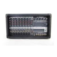
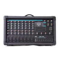
Do you have a question about the Peavey RSM 4062 and is the answer not in the manual?
Paths for signal routing, including Main, Groups, Aux, PFL/Solo, and Control Room.
Introduces the input channel stage and basic signal flow topology.
Describes the master L/R and Mono output sections, including signal paths and connections.
Explains the output mix functionality for Groups 1-4, including faders and assignment switches.
Details the stereo output mix for Groups 5 and 6 and their assignment options.
Describes the Aux 1 and 2 (Mix B) stereo mix output and its level controls.
Explains the output structure for Aux 3, 4, 5, and 6 channels.
Covers headphone, control room outputs, tape I/O, and PFL/Solo monitoring.
Explains the IEC power cord connection and safety precautions.
Describes the operation of the power switch and its associated LED indicator.
Describes the balanced XLR and unbalanced 1/4" Master L/R output connectors.
Explains the balanced XLR Mono output and its level control.
Details the control for the Mono Output level.
Describes the 1/4" TRS jacks for inserting external devices into the Master L/R signal path.
Details the unbalanced 1/4" outputs for control room monitors.
Explains the 1/4" stereo input for monitoring tape output.
Describes RCA outputs duplicating the Master L/R unbalanced output.
Details the six unbalanced 1/4" outputs for Groups 1-6.
Describes the two AUX 1/2 (Mix B) outputs, unbalanced and balanced.
Explains the four unbalanced 1/4" outputs for Aux 3-6.
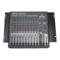
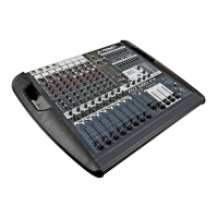
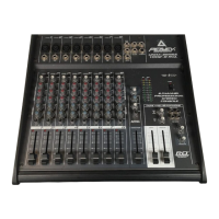
Describes back panel inputs for Super Channels 1 and 2.
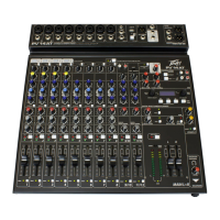
Details front panel controls and features for Channels 1 and 2.
Highlights differences and specific features for Channels 3-8 compared to Channels 1-2.
Details back panel inputs for stereo Channels 9-16.
Details front panel controls and features for Channels 9-16.
Describes the full stereo channels 15 and 16 and their unique features.
Details the 60mm faders for controlling Group 1-4 output levels.
Assigns Group post-fader signal to the Master L channel.
Assigns Group post-fader signal to the Master R channel.
Explains the PFL function within the master section for monitoring.
Details the 60mm faders for controlling Master L/R output levels.
Describes the two-channel LED peak level meter and its indicators.
Controls for setting the levels of the Aux 1/2 (Mix B L/R) channels.
Connects AUX 1/2 mix signal to the main L/R Master bus.
Switches for assigning Group 5/6 signals to various master buses.
Rotary controls for setting Group 5/6 levels to Aux 1 and Aux 2.
Details the stereo headphone output and its level control.
Control for adjusting headphone and control room output levels.
Global switch for selecting PFL or SOLO monitoring on headphone/CR outputs.
Switches for selecting monitor sources when PFL/SOLO is not active.
Controls for applying +48V phantom power to microphone inputs.
Details input impedance, gain, levels, balance, and connector types.
Details output impedance, levels, balance, connectors, gain, frequency response, and THD.
Covers S/N Ratio, Crosstalk, Common Mode Rejection Ratio, and meter characteristics.
Details what the warranty covers regarding defects in material and workmanship.
Lists items and damages that are not covered by the warranty.
Specifies that the warranty applies only to the original retail purchaser.
Outlines the warranty period based on different product categories.
Explains Peavey's actions for warranty repairs or replacements.
Provides instructions on how to seek warranty service.
States limitations on implied warranties like merchantability and fitness for purpose.
Details limitations on liability for incidental and consequential damages.
| Phantom Power | Yes |
|---|---|
| EQ | 3-band |
| Faders | 6 |
| Type | Analog |
| Power | External power supply |