EasyManua.ls Logo

Peavey XR-500

Peavey XR-500
6 pages
To Next Page IconTo Next Page
Loading...
GENERAL
DESCRIPTION
The
new
XR-500
represents
our
latest
effort
to
combine
professional
features
previously
found
only
in
separate
mixer/equalizer/power
amp
components
into
a
single
compact
ar,o
’ugaea
package.
The
design
of
the
XR-500
utilizes
ihe
latest
advances
n
semiconductor
technology
and
the
overall
circuitry
has
been
designee:
and
optimized
by
use
of
the
latest
computer
aided
design
techniques
Tms
unit’s
Improved
specifications
nave
been
made
posable
by
a
thorough
and
complete
cesicn
effort
resulting
in
ail
new
circuitry
from
the
input
jack
through
lo
the
speaker
output.
The
XR-500
features
five
mdependenl
input
channels
and
includes
a
separate
pfe”
monitor
ser\J
acbve
shelving
type
high
and
tow
equalization,
and
a
"posl‘
effects
sand
on
each
chance!
Master
level
contrc.’s
arc
provided
for
'ho
mao.
rrcoilo’
and
reverb
return
\
lull
seven-bare
graphic
equalizer
has
been
built
into
the
system
and
utilizes
Ihe
most
contemporary
active
filter
circuitry
available
Additional
flexibility
is
provided
by
the
XR-500‘s
patch
panel,
enabling
this
versalile
unit
lo
be
usee
in
cxxiiunclian
with
an
exlremey
v/idu
range
o'
auxiliary
equipment
The
newly
engineered
130-Walt
power
amplifier
features
our
exclusive
DD~^
{'
Distortion
Dotociion
Techniquca")
compression
Circuitry
that
electronically
senses
tne
onset
of
clipping
and
automa?
cany
activates
the
comrressicn
circuit
10
maximize
headroom,
and
prevent
clipp
nc
and
distortion
m
the
power
amp
The
use
of
this
DOT*
compression
circuit
efleciiveiy
increases
the
apparent
headrcom
available.
Ihus
maximizing
every
precious
Watt
of
power
available
This
compresscn
feature
alicv/s
the
XR-500
to
quite
eheclively
compete
with
un
ts
having
conscerably
more
RMS
power
The
power
amp
of
ihe
XR-500
utilizes
lour
high-voltage,
high-speed
TO-3
powpr
devices
bolted
to
a
massive
heatsink
The
internal
power
supply
consists
ol
a
very
large
pov/er
(mains)
transformer
featuring
a
grain
oriented
silicon
steel
core
and
a
high
degree
of
magnetic
shielding
to
mmmizo
extraneous
hum
fields
Siiicor
rectifiers
cornectec
in
3
ful
wave
pudge
feed
powe*
to
large
elect'olytic
Mter
banks
and
provide
considerably
more
music
pov/er
than
the
130-Watt
RMS
power
rating
would
indicate
Overall,
ihe
XR-500
brings
protessima
performance
together
m
an
exiremesy
versatile
and
compact
package,
ofiering
features
and
specifications
formerly
available
only
with
separate
componerts
in
a
single
pccable
package.
WARNING:
To
prevent
electrical
shock
or
lire
hazard,
do
not
expose
this
appliance
to
rain
or
moisture.
Question and Answer IconNeed help?

Do you have a question about the Peavey XR-500 and is the answer not in the manual?

Peavey XR-500 Specifications

General IconGeneral
TypePowered Mixer
Equalization3-band EQ per channel
Weight27 lbs (12.2 kg)
Input Impedance10k Ohms
Output Impedance4 Ohms
EffectsReverb
InputsXLR and 1/4" on each channel
OutputsMain, Monitor
Frequency Response20 Hz - 20 kHz

Summary

XR-500 General Description

XR-500 Features Overview

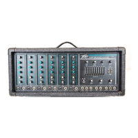
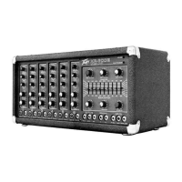
Overview of the XR-500's independent channels, equalization, and effects.

DDT Compression Circuitry

Explains the exclusive DDT compression circuitry for headroom and distortion prevention.

Power Amplifier Design

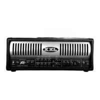
Details the power amp's TO-3 devices, heatsink, and power supply design.

Front Panel Input and Channel Controls

Input Jacks (A) and (B)

Describes the dual input jacks for flexible microphone matching and overload protection.

Channel Gain Control (C)

Adjusts input preamplifier gain for optimum dynamic range and low noise.

Channel Monitor Control (D)

Independent level adjustment for the monitor mix, feeding the monitor buss.

Channel Equalization Controls

Active shelving EQ for 15 dB boost/cut, affecting tonal balance and feedback control.

Channel Low EQ Control (E)

Boosts or cuts low frequencies; clockwise for boost, counter-clockwise for cut.

Channel High EQ Control (F)

Boosts or cuts high frequencies; clockwise for boost, counter-clockwise for cut.

Channel Effects Control (G)

Adjusts signal level to the effects bus for internal reverb and external effects output.

Master Section Overview

Controls master level, monitor, reverb return, and graphic EQ for system management.

Rear Panel Connections and Components

Auxiliary Input (M)

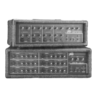
Provides access to the main mixing buss for external devices.

Effects Output (N)

Delivers output signal from the effects buss to drive line-level devices.

Monitor Output (O)

Provides a signal for an external monitor system.

Main Output (P)

Delivers output from the main mixing buss.

Graphic Input (Q)

Allows patching into the internal graphic equalizer/power amp.

Fuse (U) Location

Location and importance of the fuse for equipment protection and warranty.

Master Controls and Special Features

Master Level Control (H)

Adjusts the main mixing buss gain, affecting main output and amp input.

Master Monitor Level Control (I)

Controls the gain of the monitor mixing buss, determining monitor output level.

Master Reverb Return Control (J)

Adjusts the amount of delayed signal mixed back into the main mix buss.

Graphic Equalizer (K) Operation

Details using the master graphic EQ for room equalization, feedback control, and tone shaping.

Excessive Boost Warning

Warns about potential power amplifier overload from excessive EQ boosts.

Feedback Control Procedure

Provides a procedure for using the graphic equalizer to suppress feedback.

Pilot LED (R) Indicator

Indicates when the electrical supply is switched on and delivering power.

DDT Compression with LED (S)

Explains the DDT compression and its LED indicator for maximizing amp performance.

XR-500 Patch Panel

Designed for using auxiliary accessories, mixers, and power amps.

Footswitch Jack (L)

Input jack for an optional remote reverb cutoff pedal.

Rear Panel Switches and Connections

Power Switch (V) Operation

Explains the three-position power switch and selecting the correct position for low hum.

Line Cord (T) Safety

Importance of the three-wire line cord with proper grounding for safety and noise reduction.

Speaker Outputs (W)

Details the 1/4" speaker output jacks, their parallel wiring, and impedance considerations.

Line Cord Retainer (X)

Features on the rear panel for storing the mains cable during travel.

Safety Warnings and Specifications

Hearing Protection Warning

Emphasizes protecting hearing from high noise levels to prevent permanent loss.

General Precautions

Lists important cautions regarding water, heat, ventilation, and servicing.

Electrical Safety Precautions

Details precautions related to power cords, grounding, and potential shock hazards.

XR-500 Specifications Summary

Provides detailed technical specifications for channels, inputs, outputs, and power.

Related product manuals