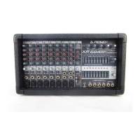
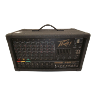
Do you have a question about the Peavey XR 886 and is the answer not in the manual?
| Type | Powered Mixer |
|---|---|
| Channels | 8 |
| Inputs | 8 XLR/line inputs |
| Equalization | 3-band EQ per channel |
| Built-in Effects | Digital effects processor |
1/4" balanced input for high-level signals. Tip is positive.
XLR balanced low-impedance input for microphones or low-level sources.
Attenuates the input signal by 20 dB to increase dynamic range.
Reverses the phase of the input signal to prevent cancellations.
High-impedance input for line-level signals, feeds left and right inputs.
High-impedance input for line-level signals, feeds right input.
Applies 40 VDC to XLR connectors to power microphones.
1/4" stereo jack for external device insertion before EQ.
Varies input gain for wide dynamic range and signal-to-noise ratio.
75 Hz low cut filter to remove rumble and mud.
Shelving EQ for treble frequencies +/-15 dB at 12 kHz.
Controls cut/boost at selected mid-frequency, +/-15 dB.
Semi-parametric sweepable mid-freq control (100 Hz to 3 kHz).
Shelving EQ for bass frequencies +/-15 dB at 70 Hz.
Adjusts channel signal level for Monitor mix (pre-EQ).
Adjusts channel signal level for Aux mix (post-fader).
Controls signal level to the digital effects processor bus.
Determines channel placement in stereo mix (Left, Right, or both).
Mutes channel signal to L&R bus, Effects, and Aux sends.
Dual function LED indicating signal level or PFL activation.
Connects channel pre-fader signal to PFL mix and headphone source.
Controls channel output level to the L&R bus.
Adjusts stereo balance for L&R bus, pan for mono signals.
Shelving EQ for bass frequencies +/-15 dB at 70 Hz.
Bandpass EQ for mid-range frequencies +/-15 dB at 1 kHz.
Shelving EQ for treble frequencies +/-15 dB at 12 kHz.
Switches stereo line inputs through channel or bypasses EQ.
Varies stereo input gain for optimal signal-to-noise ratio.
Stereo RCA input for tape deck or CD player.
Stereo RCA output for connecting to a tape deck.
XLR connector for low voltage lamps.
Adjusts tape signal level to the L-R mix.
Sets main stereo signal level to tape output jack.
LEDs indicate frequency band energy for feedback identification.
Mutes signal to tape out jack to prevent feedback during recording.
9-band equalizers fixed on 1 octave centers for tone shaping.
Adds tape signal sum to Aux 1 or Aux 2 monitor mixes.
Configures unit as stereo or dual mono amplifier.
12-segment arrays monitor main L-R output levels.
Controls Aux 1 mix output level.
LED indicates Aux PFL assignment or 2 dB headroom.
Connects effects output to PFL mix and switches headphone source.
LED indicates effects PFL assignment or 6 dB headroom.
Connects digital effects output to PFL mix.
Mutes effects signal from processor to L-R and sends.
Selects presets for reverb, delay, and effects.
Adjusts reverb/delay time or chorus/phaser/flange rate.
Controls effects mix output level to digital processor.
Controls digital effects output level to L&R bus.
Sends digital effects signal to monitor mixes.
Adjusts reverb damping, delay feedback, or depth/width.
LEDs for monitor overload or PFL activation.
Connects monitor signal to PFL mix.
Sets overall level for Monitor 1 & 2 signals.
Faders set level of left/right mix output.
Adjusts mono mix output level.
Adjusts headphone output volume.
Stereo jack for headphones, switches to PFL when active.
Sets level of PFL mix sent to headphone control.
LED indicates PFL signal overriding L-R mix.
Power on LED indicator.
1/4" balanced outputs for Left and Right mixes.
1/4" balanced outputs for Monitor 1 and 2 mixes.
XLR balanced output for the mono mix.
Attenuates Mono output signal by 30 dB.
Unbalanced output for Aux mix, feeds external units.
Jack for footswitch to control effects board or Rotary Speaker.
Jacks break connection between preamp and EQ inputs.
Jacks connect to speaker cabinets, min. 4 ohms impedance.
Connect microphones and line-level sources for live sound.
Connecting mics to XLR inputs, line to 1/4" inputs, using pad/polarity.
Connecting to main outputs or mono output for additional amplification.
Connecting monitor amps to Mon 1/2 outputs.
Connecting external effects to Aux 1 output.
Connecting effects outputs to channel line inputs.
Connecting tape recorder to Tape input/output jacks.
Using inserts on channels 1-4 for compressors or EQ.
Using Aux 1 as an additional sub mix.
Connecting outputs to two-track mixdown deck inputs.
Input impedance, gain range, levels, and connector type.
Input impedance, gain range, levels, and connector type.
Input impedance, gain range, levels, and connector type.
Input impedance, gain range, levels, and connector type.
Input impedance, gain range, levels, and connector type.
Output impedance, levels, and connector type.
Output impedance, levels, and connector type.
Output impedance, levels, and connector type.
Output impedance, levels, and connector type.
Output impedance, levels, and connector type.
Output impedance, levels, and connector type.
Output impedance, levels, and connector type.
Details input gain adjustment ranges for various inputs.
Specifies frequency response for different outputs.
THD values for mic to L-R output.
Details EQ filter bandwidth, frequencies, and limits.
Specifies power output, gain, and distortion.
Details DDT dynamic range, hum/noise, cooling, protection.
Residual noise levels for outputs under various conditions.
EIN value for mic inputs.
Measures adjacent channel and left/right output crosstalk.
CMRR values for mic inputs.
Description of L/R Master meter type and reference.
Details LED indicator behavior for clipping.
Specifies voltage and current for lamp connector.
Details voltage, frequency, and wattage for domestic/export.
Warranty for product defects, excluding certain parts.
Warranty for tubes and meters.
Conditions that void the warranty and limitations.
How to register the product for warranty service.
General guidelines for safe operation and handling of the product.
Information on potential hearing loss from high noise levels.