© COPYRIGHT 2008 PECO, INC. ALL RIGHTS RESERVED. P/N 69387 3220-2124 REV 0 PAGE 2
JP3 Jumper Selection – HVAC Setback Systems: The JP3 jumper
allows the T180 to be congured for Setback, Occupancy Detection or
Door Switch Only Occupancy Operations. For further descriptions of
these conditions please see the Technical/Application Section.
Setback Operation - Remove JP3
Occupancy Detection - Install JP3
Door Switch Only - Install JP3
JP4 Jumper Selection – 2 or 4 Pipe Operation: Connection of a pipe
sensor will change the operation of the outputs as shown in the table
below. (See Technical Notes for further information on Pipe Sensor
Operation)
2-Pipe Operation - Install JP4 - The thermostat will permanently
disable the Secondary Output and disables system and fan invalid
modes.
4-Pipe Operation - Remove JP4 - Both the Main Output (COOL)
and Secondary Output (HEAT) will be available.
Secondary
Output
(Red Wire)
* Fan will not cycle o n for disabled modes.
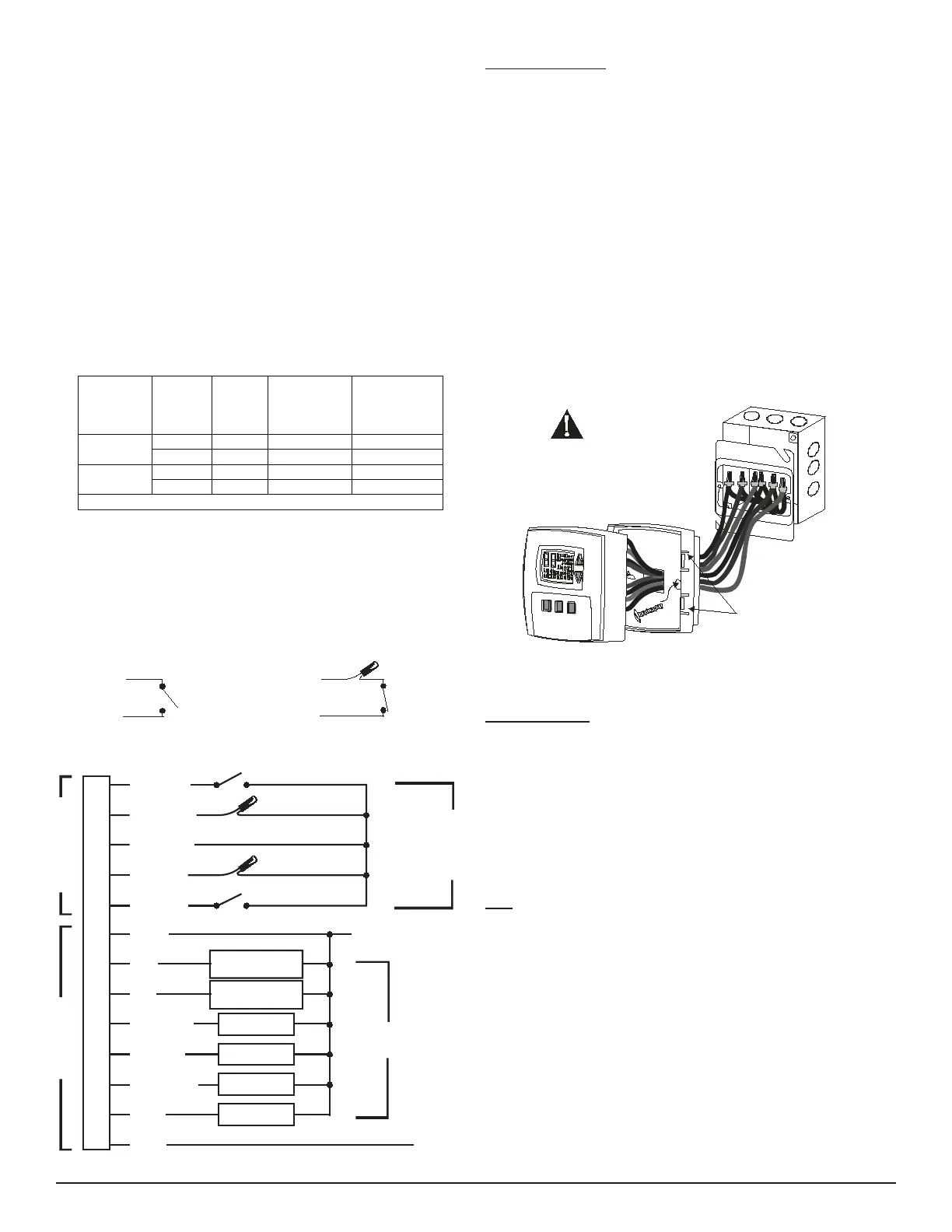
Condensate Overow Interrupt - The remote probe input can be used
with a condensate overow interrupt switch (CO), either in conjunction
with a remote probe (normally closed CO switch) or with local sensing
(normally open CO switch). When the condensate switch activates, the
T180 will display the service wrench and disable all outputs
Whit e/Yellow
Whit e/Violet
Remote Probe
Circuit Common
Normally
Closed
Condensate
Switch
Remote Probe Installation
Whit e/Yellow
Whit e/Violet
Remote Probe
Circuit Common
Normally
Open
Condensate
Switch
Local Sensor Installation
•
•
•
•
•
▲
!
Mounting Thermostat
Thermostat mounts to a 4” x 4” box with a 2” x 4” mud ring. Adapter
wall plates are available if needed.
Pull wires through the hole of the thermostat base.
Mount thermostat base to the wall using the enclosed mounting
screws. Tighten screws evenly but do not over tighten.
Verify that the circuit board is rmly snapped into the cover and has
not been dislodged during handling.
Match and connect equipment wire thermostat using the appropriate
wiring schematic as shown at the bottom of the page on the left-
hand side.
Wire nut all unused wires or terminate properly according to local
building codes.
Mount the base to the mud ring and install the cover assembly.
Firmly press cover to engage the cover locking snaps. Should the
cover need to be removed in the future, use a at edged tool to
put pressure on the base sides. This will release the four side
latches.
Turn on power to equipment.
CAUTION
2x4 Mud Ring
T180 Base
T180 Cover Assembly
All wiring connections must be made
inside the electric box or the T180
maybedamaged.
Cover Locking Snaps
(Both Sides)
System Check-out
After wiring and installation is complete, energize the system.
Set fan to ON. Select each fan speed (TA180 Models) to verify
operation.
Set the System button to AUTO, or available selection.
Using the UP arrow, adjust temperature more than 5°F above the
room temperature to cycle on heating.
Using the DOWN arrow adjust the temperature to 5°F below room
temperature to cycle on cooling.
Note: If the thermostat is set to utilize a time-based purge cycle (Service
menu 16), the thermostat will conduct a 3-min purge on initial start-up if a
pipe sensor is connected.
THERMOSTAT CONFIGURATION / SERVICE MENU
To enter the Service Menu press the UP and DOWN arrows simultaneously
for ve (5) seconds. The current display icon will be turned off.
Service menu numbers 1 through 18 are available. Push the SYSTEM
button to move to the next Service Menu number. The UP and DOWN
arrow keys will scroll through your range of options for each feature. The
selection that is ashing is the one you are selecting. All changes to
the Service Menu are automatically saved when the system times out.
Please refer to the service menu table on page three.
1.
2.
3.
4.
5.
6.
7.
8.
1.
2.
3.
4.
5.
Black
Yellow
White/Black
White/Blue
White/Gray
Blue
Red
White/Brown
White/Red
White/Orange
Brown
L1
L2 / NEUTRAL
Setback Input/ Door Switch
Pipe Sensor
Occupancy Detector
Cool
(
Main Output)
Heat
(Secondary Output)
Fan Low
Fan Medium
Fan High
Outside Air
THERMOSTAT CONNECTIONS
LOW VOLTAGE LINE VOLTAGE
White/Yellow
White/Violet
Remote Probe
Circuit Common
OUTPUTS
See Ratings
Accessories
Available
from
PECO
 Loading...