1.InstalltheT155withthetwofurnishedmountingscrewstoa
standard
2”x4”electricalbox,4-11/16”x2-1/8”squaredevicebox
with
a2”x4”adapterringortoa4”x4”boxwithaccessoryadapter
plate.
2.For
wallinstallations,mountthethermostatonaninsidewall
approximately
5feetabovetheoor.
The
locationshouldprovide
circulation
ataverageroomtemperature.
A
voiddirectsunlightor
sources
ofhotorcoldairintheroomorwall.
3.Removetheknobandthenthecover.Mountthermostatbase
assembly
totheoutletboxusingthescrewsprovided,tightenthe
screws
evenlybutdonotovertighten.Makewiringconnectionsas
noted.
4.T
ousearemotesensor,removejumperJP-1todisablelocal
sensing.
FailuretoremoveJP-1whenusingaremotesensorwill
cause
improperoperationofthethermostat.Someunitsdonothave
remotesensingcapability.SeeApplicationNotes.
5.Reinstallthecoverassembly.Installcoverlockingscrewprovided.
Reinstall
theknob.
© Copyright 2010 PECO, Inc. All Rights Reserved P/N 68798 3220-1449 Rev2 Page 1
Installation Instructions
TA155/TB155
•READTHESEINSTRUCTIONSCAREFULLYBEFOREATTEMPTINGTO
INST
ALL,OPERATEORSERVICE
THIS
THERMOST
AT.
•Failure
toobservesafetyinformationandcomplywithinstructionscould
result
inPERSONAL
INJURY,DEATH
AND/OR
PROPERTY
DAMAGE.
•Toavoidelectricalshockordamagetoequipment,disconnectpowerbefore
installingorservicing.
•Toavoidelectricshockordamagetoequipment,useonlywiringwithinsula-
tionratedforfullthermostatoperatingvoltage.
•Toavoidpotentialfireand/orexplosiondonotuseinpotentiallyflammableor
explosive
atmospheres.
•Retaintheseinstructionsforfuturereference.Thisproduct,wheninstalled,
will
bepartofanengineeredsystemwhosespecificationsandperformance
characteristics
arenotdesignedorcontrolledbyPECO,Inc.
Y
oumust
review
yourapplicationandnationalandlocalcodestoassurethatyour
installation
willbefunctionalandsafe.
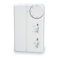
TemperatureRange:50°F-90°F(10°C-32°C)
TA155:
A
HEAT-OFF-COOL
systemswitchmanuallyselectsheating
or
coolingmode.IntheHEAT
position,onlytheheatoutputcycles
with
demand.IntheCOOL
position,onlythecooloutputcycleswith
demand.IntheOFFposition,heatingandcoolingoutputsareoff.Units
with
atwopositionsystemswitchorwithoutasystemswitchmustuse
a
loadtransferswitchwhenbothheatingandcoolingoutputsareused.
This
preventscontrolfailureandequipmentdamagecausedbydirect
cycling
betweenloads.
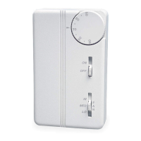
TB155:
An
ON-OFFsystemswitchenablesauto-changeoverofheating
and
coolingmodes.IntheONpositionthethermostatactivatesheating
or
coolingoutputsdependantupontherelationshipbetweensetpoint
and
ambienttemperature.Heatontocoolondeadbandis4°F.In
theOFFposition,heatingandcoolingoutputsareoff.Unitswithout
a
systemswitchcyclebetweenheatingandcoolingwitha4°Fdead
band.
F
AN:Someunitshaveaswitchformanualselectionoffanspeed.On
theseunitsfanoperationiseitherinternallywiredforfancontinuous
operation
orisdependantuponconnectiontothefansupplyinput.
When
internallywiredforfancontinuousoperation,thefanwillbe
of
fwhenthesystemswitchisoff.Whendependantuponexternal
connections
thefanmaynotbeoffwiththesystemswitchintheoff
position.Thefansupplyinputisswitchedtofanspeedoutputs(HI-
MED
-LO).
SWITCHEDPOWER:L1powerisswitchedtothisoutputanytimethe
system
switchisoutoftheOFFposition.
Whenremovingandre-installingtheT-155
knob,
caremustbetaken.
•Align
arrowto70°Fontheknob(22C)or
midrange
whenremovingtheknob.
•Reinstallknobbyaligningarrowto70°F
(22C)ormidrange.
•Do
notforceit.Whenproperlyaligned,the
knob
willslipintoposition.
Align arrow to 70°F
on the knob (22C)
•UseCopperwire
only
,insulateorwire
nut
allunusedleads.
•Anywiring,including
the
remoteprobe,
maycarrythefull
operating
voltageof
the
thermostat.
▲
▲
▲