The valve is to be installed as shown in Figure 4.2.
Pipe the discharge of the relief valve to within 12" of
the floor and close to a floor drain.
Provide piping that is the same size or larger than the
relief valve outlet.
9. Circulator: The boiler circulator is to be sized to
overcome the pressure drop of the system while
providing the flow required by the boiler.
a. If the boiler is piped in a secondary loop of a
primary/secondary heating system, the circulator
will need only to overcome the resistance of the
boiler and any fittings in that loop.
b. The circulator should be sized based on the net
output of the boiler. Table 4.3 shows the Boiler
Output as reported to the Hydronics Institute
Section of AHRI. These values are based on a
pickup factor of 1.15.
c. The required flow is calculated based on the
design temperature difference from the return to
the supply of the boiler. For a PF-110 with a
design temperature difference of 20°F the
calculation is as follows.
Output 88,000
Required Flow =
_________
=
________
= 8.8 GPM
D
T x 500 20 x 500
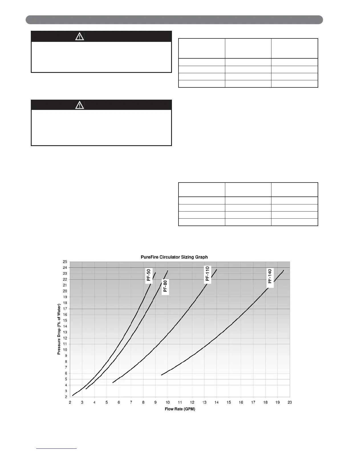
d. Table 4.4 shows the pressure drop (in feet of
water) for a flow rate for each boiler model that
produces a temperature difference of 20°F.
e. The boiler pressure drop for various flow rates can
be determined using Figure 4.3, the P
UREFIRE
Boiler Circulator Sizing Graph.
12
WATER PIPING AND CONTROLS
PUREFIRE
Model
Boiler Input
Btu/hr (kW)
Net I=B=R
Output
Btu/hr (kW)
PF-50 50,000 (14.7) 40,000 (11.7)
PF-80 80,000 (23.4) 64,000 (18.8)
PF-110 110,000 (34.2) 88,000 (25.8)
PF-140 140,000 (41.0) 113,000 (33.1)
Table 4.3: Boiler Inputs and Outputs
Table 4.4: Flow Rate and Pressure Drop at 20°F
Temperature Rise
Figure 4.3: PUREFIRE Circulator Sizing Graph
Do not operate this appliance without installing the
pressure relief valve supplied with the boiler or one
with sufficient relieving capacity in accordance with
the ASME Rating Plate on the boiler heat exchanger.
WARNING
Pipe the discharge of the relief valve as close as
possible to the floor and away from high traffic areas.
Pipe the discharge to a floor drain. Failure to do so
may result in personal injury and/or property
damage.
CAUTION
PUREFIRE
Model
Flow Rate
GPM (LPM)
Pressure Drop
Feet (Meters)
PF-50 4.0 (15.1) 5.1 (1.6)
PF-80 6.4 (24.2) 10.2 (3.1)
PF-110 8.8 (33.3) 10.0 (3.0)
PF-140 11.3 (42.8) 7.0 (2.1)