A. GENERAL
1. The disposal of all condensate into public sewage
systems is to be in accordance with local codes and
regulations. In the absence of such codes, follow these
instructions.
2. Proper piping and removal of condensation from
combustion is critical to the operation of a condensing
appliance. Follow these instructions carefully to assure
that your P
UREFIRE boiler operates correctly.
3. Depending on several factors, the condensate from
gas fired condensing appliances may have a pH value
as low as 2.5 (similar to cola soft drinks). Some local
codes require the use of neutralization equipment to
treat acidic condensate.
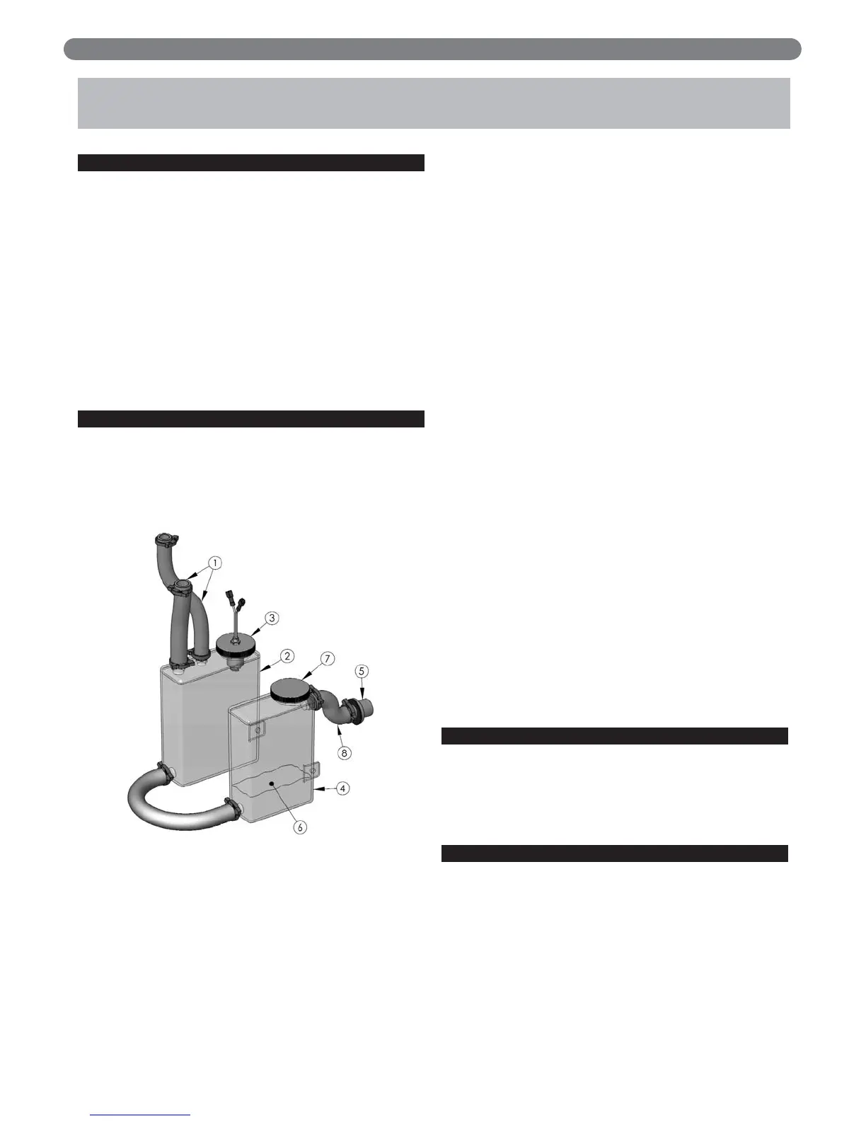
B. CONDENSATE SYSTEM
The PUREFIRE condensate system is designed to prevent
condensate from backing up into the heat exchanger, trap
the condensate to prevent combustion gases from
escaping and neutralize acidic condensate. Refer to Figure
6.1 for an illustration of the system components.
1. Condensate Drain Hoses: There are two condensate
drain hoses attached to the heat exchanger. The first
drains condensate from the combustion chamber of
the boiler. The second drains condensate from the
vent system. This prevents dirt and debris from the
venting system from entering the heat exchanger and
fouling the heating surface.
2. Condensate Collector Container: The condensate
collector container is a transparent container in the
base of the boiler near the back. This container
collects the condensate and acts as a part of a trap to
prevent combustion gases from escaping. The
container is fitted with a level switch that will prevent
the boiler from operating if the condensate line is
clogged.
3. Condensate Float Switch: This switch will prevent the
boiler from operating if the condensate outlet is
clogged before the level of condensate reaches the
heat exchanger.
4. Condensate Neutralizer Container: The condensate
neutralizer container is an additional transparent
container near the front of the boiler. Fill this
container with the condensate neutralizer provided.
The neutralizer will be consumed during normal
operation and should be checked occasionally to
determine if additional neutralizer is necessary.
Neutralizer is available in 1 lb bags (#54159) from
your PB Heat Distributor.
5. Bulkhead fitting: The bulkhead fitting allows the
condensate tubing to pass through the jacket without
providing a path for leakage from the jacket. A PVC
TEE is to be attached to the outlet of this fitting to
prevent siphoning of the trap.
6. Neutralizer: Condensate neutralizer is provided in a
package with the boiler to fill the condensate
neutralizer container (Item 4).
7. Neutralizer Cap: This cap provides access for adding
and inspecting the condensate neutralizer.
8. Condensate Drain Tube: This pre-formed tube
connects the condensate system to the bulkhead
fitting for attachment to an external drain.
C. CONDENSATE DRAIN PIPE MATERIAL
The condensate drain is to be piped using PVC,
polypropylene, or other material resistant to acidic
condensate. Do not use steel, brass or galvanized pipe for
this purpose. The acidic condensate will attack most
metals and corrode.
D. CONDENSATE DRAIN PIPE SIZING
The bulkhead fitting for condensate connection is for 3/4"
schedule 40 PVC Pipe. Be sure to use 3/4" or larger
tubing from the boiler to the drain.
24
CONDENSATE DRAIN PIPING
6. CONDENSATE DRAIN PIPING
Figure 6.1