33
C. BOILER CONTROL
1. Pump Modes:
The P
UREFIRE control enables the installer to choose
from 3 different pump modes depending on the
installation. Table 8.3 provides a brief overview of the
3 available pump modes. The following are detailed
explanations of the pump modes.
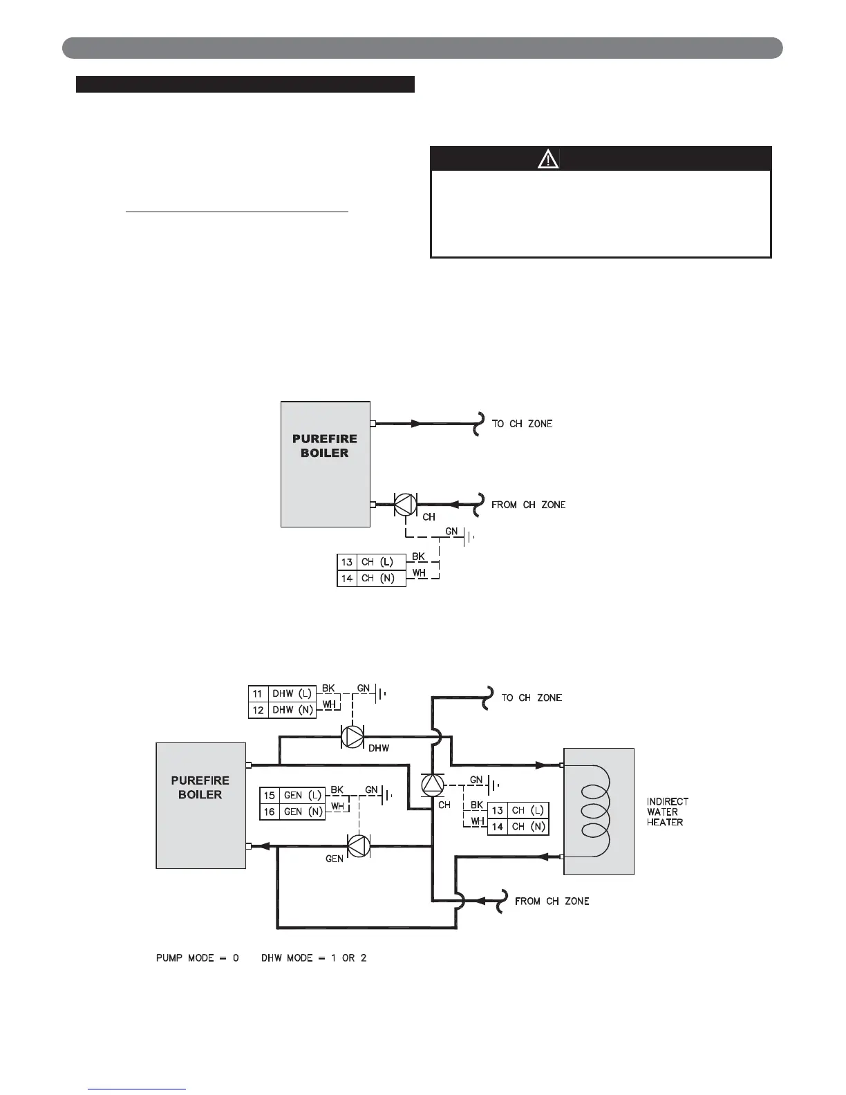
Pump Mode 0 – CH or CH&DHW pump:
This mode is intended for a single heating zone with,
or without, a DHW tank. Figure 8.2 shows typical
piping for a single zone without DHW. Figure 8.3
shows typical piping for a single zone with DHW.
In this case, circulation through the boiler is to be
provided by the CH pump when in a central heating
mode. When satisfying a DHW demand, the
circulation through the boiler is provided by the
DHW pump.
Figure 8.2 & 8.3 both show the electrical connections
from the boiler to the circulators. Either the CH pump
or the DHW pump can be energized but they can
never run simultaneously.
BOILER CONTROL: INTERNAL WIRING & OPERATION
The CH and DHW circulator must be sized correctly
to provide the minimum flow required through the
boiler. If the boiler is not piped primary/secondary do
not rely on the pump recommendations in Section 4,
Water Piping.
NOTICE
Figure 8.2: Pump Mode = 0, DHW Mode = 0
Figure 8.3: Pump Mode = 0, DHW Mode = 1 or 2