35
2. Installation Location & Vent Material:
The P
UREFIRE boiler allows the installer to input the
installation location and the vent material used. This
information is used to determine the suitable vent
temperature limit based on National Codes. Table 8.6
shows the vent temperature limit based on the
location and vent material.
The P
UREFIRE control will reduce the boiler firing rate
if the vent temperature approaches the vent
temperature limit. If the vent temperature continues to
rise, the control will shut down the boiler.
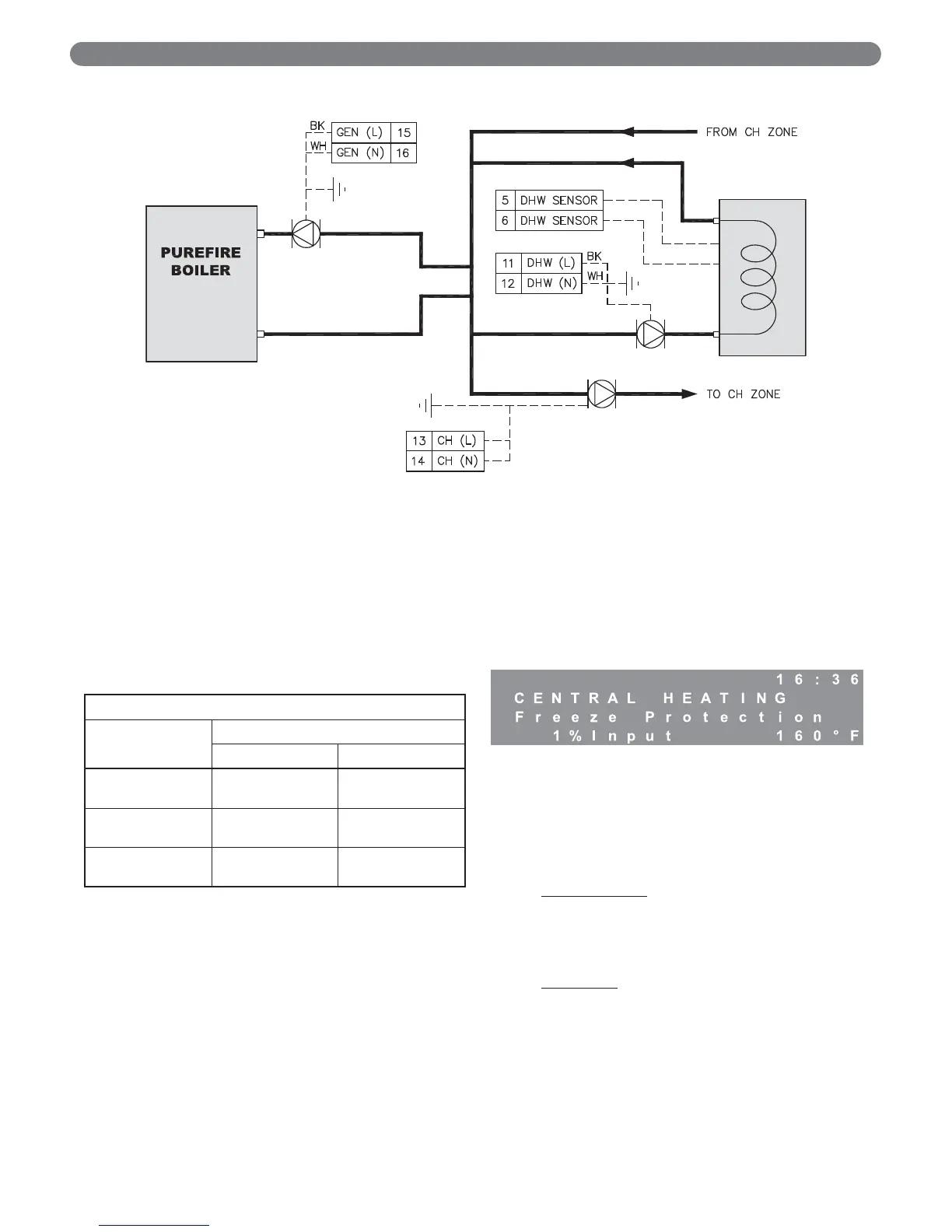
3. Freeze Protection:
The P
UREFIRE boiler control is intended to prevent the
central heating system from freezing. The default
temperature to activate this function is 50°F (10°C).
If the supply temperature drops to below the freeze
protection setpoint, the general pump and/or the CH
pump (depending on pump mode) will be activated. If
the supply or return temperature drops more than 9°F
(5°C) below the setpoint, the control lights the boiler
using the ignition sequence described in section 8.B.
The control will operate the burner at minimum
power until the both the supply and return boiler
temperature are more than 9°F (5°C) above the freeze
protection setpoint.
While this function is active the interface panel will
display the following:
4. Additional Safety Functions:
The P
UREFIRE boiler control is equipped with terminals
for either a low water cutoff or a flow switch. The low
water cutoff option is the factory default and a factory
supplied jumper is installed. This jumper is to be
removed if a low water cutoff or flow switch is
installed.
Low Water Cutoff
: The installer can connect the
power supply wires for a probe-type low water cutoff
to terminal #19 (Hot) and #20 (Neutral) in the main
terminal box. The contacts should be wired to
terminals #9 and #10.
Flow Switch:
If a flow switch is used, simply wire the
contacts to terminals #9 and #10 in the main
terminal box.
BOILER CONTROL: INTERNAL WIRING & OPERATION
Figure 8.7: Pump Mode = 2, DHW Mode = 1 or 2
Table 8.6: Vent Temperature Limits
Vent Limit Temperature
Vent
Material
Location
U.S.A. Canada
PVC
195°F
(90°C)
149°F
(65°C)
CPVC
230°F
(110°C)
195°F
(90°C)
PP(s)
230°F
(110°C)
230°F
(110°C)