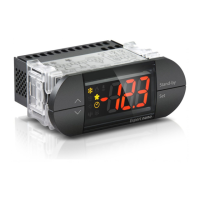
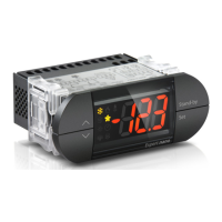
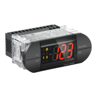
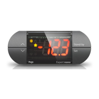
Expert nano LINE
200NANO4CK1*
Termoregolatore elettronico / Electronic thermostat
Manuale d’uso e manutenzione / Use and maintenance manual
Via Piacentina, 6/b - 45030 - ROVIGO
Tel : +39(0)425 762906 - Fax: +39(0)425 762905
www.pego.it - e-mail: info@pego.it
200NANO4CK1#_02-13_ITA_ENG # Rev.02-13 # 29/04/2013
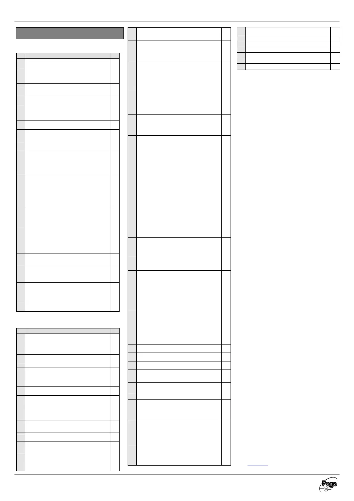
LIST OF FIRST LEVEL VARIABLES
(User level)
Var
DEF.
r0
Temperature differential in rela
SET-POINT
< Range: 0.2 ÷ 10°C >
Expressed in absolute values and defines hysteresis
(positive if mOd=0 or negative if mOd=1) of
temperature in relation to SET POINT.
2
d0
< Range: 0 ÷ 24 hours >
4
d2
< Range:-35 ÷ 45°C >
Defrosting is not performed if the temperature read
by the defrosting probe is higher than value d2. (In
the event of a defective probe, defrosting is
performed on a time basis.)
15
d3
25
d7
< Range:0 ÷ 10 min >
At completion of defrosting the compressor and fans
remain inactive for the set period of time d7 and the
defrosting LED on the front of the board flashes.
0
F5
< Range: 0 ÷ 10 min >
Keeps fans inactive for a period of time F5 after
dripping. This period is timed from the end of
dripping. If dripping is not set, the fans pause directly
0
A1
Minimum temperature alarm
< Range: - 45 ÷ (A2-1)°C >
Absolute temperature referred to by the ambient
probe below which, following the ALD delay, the
LOW temperature alarm is triggered, activating the
buzzer (if present) and showing the letters EL
alternating with the temperature on the disp
well as the flashing alarm icon.
-45
A2
Maximum temperature alarm
< Range: (A1+1) ÷ 99°C >
Absolute temperature referred to by the ambient
probe above which, following the ALD delay, the
HIGH temperature alarm is triggered, activating the
buzzer
(if present) and showing the letters EH
alternating with the temperature on the display, as
well as the flashing alarm icon. When the alarm is
reset the alarm icon remains on without flashing to
indicate that the event occurred, until the UP key is
99
tEu
Evaporator probe temperature display
< °C >
(does not display anything if dE =1)
reading
only
dFr
Evaporators defrost enabling in real time
With d0=0 and dFr=1 it is possible to set up until 6
defrosts in real time
0
dF1.
.6
Evaporators defrosts times programming
It is possible to set up to 6 times for defrosts (from
00,0 ÷ 23,5 )
The time is in the mode HH.M where HH represents
the hour and M the ten minutes(i.e. 0=0 min.; 1=10
min. etc.). The wink
ing point (.) shows that it is
displayed a time and not a temperature.
0
LIST OF SECOND LEVEL VARIABLES
(Installer level)
Var
DEF.
F3
Fan status with compressor off
< Range: 0 ÷ 2 >
0 = Fans in continuous operation
1 = Fans ON only with compressor ON
1
F4
Fan pause during defrosting
0 = Fans ON during defrosting
1 = Fans OFF during defrosting
1
Fst
The fans remain disabled if the temperature value
read by the ev
aporator probe is higher than the value
of this parameter. The fans are re-
evaporator probe deactivated or in error mode.
45
Fd
2
dE
Evaporator probe exclusion
0 = Evaporator probe present
1 = Evaporator probe absent
By excluding the evaporator probe, defrosting
occurs cyclically based on d0 period and
terminates upon the elapse of d3 time.
0
d1
0= Heating element
1= Cycle inversion (hot gas)
0
C1
Minimum time between each turning off and on of
0
CE1
Duration of compressor ON time in the case of faulty
ambient probe (emergency mode).
< Range: 0 ÷ 240 min / 0=Disabled >
If CE1=0 the emergency mode in the pres
error EO remains disabled, the compressor
remains off and defrosting is prevented in order to
conserve the remaining cold.
0
CE2
Duration of compressor OFF time in the case of faulty
ambient probe (emergency mode).
5
doC
essor timeout due to door switch opened
< Range: 0 ÷ 5 min >
When the door switch opens, the evaporator fans
turn off and the compressor continues to function
for a period doC, after which it turns off.
0
Tdo
activation time after door opene
< Range: 0 ÷ 240 min / 0=Disabled > (with dO2=0)
When the door switch opens and after the time
tdo, normal function of the control is restored,
generating the door open alarm (Ed).
Delay time of cold room light alarm signalling and
visualization (with dO2=1)
< Range: 0 ÷ 240 min / 0=Disabled >
On switching on of the light with UP key and
passed the Tdo time, the E9 alarm starts. If it has
silenced and the light has not swiched off on new
Tdo time limit, the alarm starts again. If dO2 is set
y, the E9 alarm will excite the relay.
0
mOd
Thermostat functioning mode
< Range: 0 ÷ 1 >
0 = Cold function
1 =
Hot function (in this mode defrosting and fan
disable Fst are excluded)
0
In1
Digital Input DI and activation mode setting
< Range: -6 ÷ 6 >
7= Pump-down pressure switch (with DI=1)
6= Stop defrosting remotely (DI=1)
(reads leading edge of impulse)
5= Start defrosting remotely (DI=1)
(reads leading edge of impulse)
4= Stand-by remotely (DI=1)
(In order to indicate Stand-
shows IN4 alternating with the current view)
3= Man-in-room alarm (DI=1)
2= Door switch (DI=1)
1= Compressor protection (DI=1)
0= Disabled
-1= Compressor protection (DI=0)
-2= Door switch (DI=0)
-3= Man-in-room alarm (DI=0)
-4= Stand-by remotely (DI=0)
(IN4 alternating with the current view is
displayed to indicate stand-by mode)
-5= Start defrosting remotely (DI=0)
(reads leading edge of impulse)
-6= Stop defrosting remotely (DI=0)
(reads leading edge of impulse)
down pressure switch (with
1
dO2
Digital Output DO3 setting
< Range: 0 ÷ 1 >
0= Defrosting heating elements output
1= Room light output (automatically activated
when the door is open or with the man in room
alarm E8) (see parameter Tdo)
2= NO ALARM output (it closes when the alarm is
0
dO4
DO4 digital output operation settings
(OUTPUT WITH POTENTIAL-
Range: -2 ÷ 4
4= DO4 energised relay with activated cold
function (evaporator solenoid). The DO1 output is
activated by the digital input, set in 1 as Pump-
down pressure switch (In 1=7 or –7)
3= Light room output (It is automatically activated
when the door is open and with the man in room
alarm E8)
2= DO4 energised relay with DO1 energised
compressor output. Used for motor condenser
unit.
1= DO4 relay energised in alarm presence
0= DO4 relay Deactivated
-1= DO4 relay de-energised in alarm presence
-2= DO4 relay de-energised with DO1 energised
compressor output. Used for carter resistance
0
LSE
Minimum value attributable to set point
-45
HSE
Maximum value attributable to set point
45
CAL
Ambient probe value correction
0.0
Ald
Delay time for signalling and display of minimum
and maximum temperature alarm
120
Ad
Network address for connection to TeleNET or
Modbus supervision system
< Range: 0 ÷ 31 (SEr=0)
0
SEr
485 communication protocol
< Range: 0 ÷ 1 >
0= TeleNET protocol
1= Modbus-RTU protocol
2= ECHO enable ( RS485 disable)
0
P1
Password: protection type
( active when PA is different from 0)
< Range: 0 ÷ 3 >
0= Displays only the set point and allows alarm
stop
1= Displays the set point, allows alarm stop, +
defrost + light
2= Blocks access to levels 1 and 2 during
programming (all other functions permitted)
3= Blocks access to level 2 during programming (all
other functions permitted)
3
PA
(see P1 for protection type)
< Range: 0 ÷ 999 / 0=Disabled >
0
Yr
0…99
Mo
1…12
dy
1…31
Hr
0…23
min
0…59
reL
Release software
THERMOSTAT FUNCTION MODES (mOd)
The variable mOd allows the selection of function mode of the
thermostat, in particular:
COLD MODE (mOd=0)
The DO1 output is activated when the temperature measured
by the ambient probe reaches or exceeds the SET POINT+r0
value and remains active until the temperature drops below the
SET POINT. In this mode, the DO1 output is linked to the cold
function icon.
HOT MODE (mOd=1)
The DO1 output is activated when the temperature measured
by the ambient probe reaches or exceeds the SET POINT-r0
value and remains active until the temperature increases and
exceeds the SET POINT. In this mode, the DO1 output is linked to
the hot function icon; defrosting and fan stop FSt are DISABLED.
DIGITAL OUTPUT FUNCTION SETTINGS (dO2)
The variable dO2 allows the allocation two possible functions to
digital output DO2 on the basis of its value: 0=defrosting heating
elements output and 1=room light output.
In systems with off-
cycle or fan defrosting, therefore, dO2=1
can be set to enable the UP key function for the room light. If
this key is pressed for longer than 3 sec, it activates/deactivates
the room light (output DO2) and controls the relative ROOM
LIGHT icon. If the light is manually turned on/off, a BIP is
generated as confirmation. When configured for the room light,
the dO2 output is automatically activated when the door switch
input is active or the man-in-cell alarm is triggered (E8).
PASSWORD FUNCTION
The password function is activated by entering a value other
than 0 for the PA parameter. See parameter P1 for various
protection levels. The protection is activated automatically if the
keyboard remains inactive for about 30 seconds. The figure 000
appears on the display. Use the up/down keys to change the
number and the SET key to confirm. The password entry
template 000 disappears if the keyboard is not activated within
30 seconds.
If you forget the password, use the universal number 100.
EMERGENCY MODE IN THE CASE OF ERROR EO
This safety mode guarantees the functioning of the compressor
even in the case of a faulty ambient probe (error EO). If probe
errors E0 and CE1 are different to 0, the compressor functions in
operation pause mode, with compressor ON for the time CE1
and OFF for the time CE2. If CE1>0 in the case of error E0,
defrosting is performed in normal functioning mode. If CE1=0
the emergency mode in the presence of error E0 remains
disabled. The compressor remains off and defrosting is
prevented to conserve the remaining cold. Eliminate as soon as
possible the cause of error E0 and reactivate the control’s
normal function for a correct temperature adjustment.
MANUAL DEFROSTING ACTIVATION
To activate defrosting simply press the DOWN key for more than
30 seconds; this activates the heating elements relay. Defrosting is
not activated if the appropriate conditions are not present (end-of-
defrosting temperature (d2) set lower than the temperature read
by the evaporator probe). Defrosting terminates when the end-of
defrosting temperature (d2) is reached or for a maximum
defrosting time (d3) or by manually forced end-of-defrosting (end-
of-defrosting key or digital input).
MANUALLY FORCED END OF CURRENT DEFROSTING
Pressing the DOWN key for 3 seconds durin
the end of the current defrosting. In the case of manual end-of-
defrosting, dripping is also excluded.
HOT GAS DEFROSTING
Set the parameter d1 =1 to control inversion cycle defrosting.
During the entire defrosting process the compressor and defrost
relays are activated. For a correct control of the system, the
installer must use the defrost output which must allow the
opening of the inversion cycle electrovalve and closing of the
liquid electrovalve. For capillary systems (without thermostatic
valve) it is sufficient to control the inversion cycle electrovalve
using the defrost relay command.
AMBIENT TEMPERATURE DISPLAY DURING AND AFTER
DEFROSTING
During defrosting and for a minute following the end of
defrosting, the display continues to display the last ambient
temperature value read before start of defrosting.
RS-485 CONNECTION
Connection to a RS485 network must be chain type, avoiding
star connections and observing A and B polarity. It is advisable
to use BELDEN 8762 cables. The configuration of the device in
the TeleNET program is performed by entering the module
name such as “Expert Nano 3 CF device” and assigning to it the
same network address entered in the variable Ad. For a
Modbus-RTU network connection and for details on the
protocols of these devices, refer to the manual “MODBUS-
RTU_NANO1RTC” which can be downloaded from our internet
site at
www.pego.it.
 Loading...