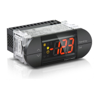
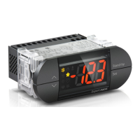
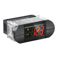
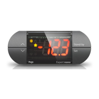
Expert nano LINE
200NANO4CK1*
Termoregolatore elettronico / Electronic thermostat
Manuale d’uso e manutenzione / Use and maintenance manual
Via Piacentina, 6/b - 45030 - ROVIGO
Tel : +39(0)425 762906 - Fax: +39(0)425 762905
www.pego.it - e-mail: info@pego.it
200NANO4CK1#_02-13_ITA_ENG # Rev.02-13 # 29/04/2013
PEGO S.r.l. does not accept responsibility for
information, costs of goods or substitute services, damages to
objects, persons or animals, lost sales or profits, interruption of
activities, any direct, indirect, accidental, property, insured, punitive,
special or consequential dama
ge caused in any way, be it contractual,
extra-
contractual or due to negligence or other responsibility
resulting from the use of the product or its installation. The guarantee
automatically becomes invalid in the case of poor functioning due to
tampering,
impact or inadequate installation. It is mandatory to
observe all instructions in this manual and the operating conditions of
the device. PEGO S.r.l. does not accept responsibility for any
inaccuracies which may be present in this manual in the case that
these are due to printing or transcription errors and reserves the right
to make modifications to its products which it deems necessary or
appropriate, without prejudicing the products essential
characteristics.
ELECTRICAL PRESCRIPTIONS
Avoid using multi
polar cables with conductors connected to inductive
and power loads and signal conductors such as probes and digital
inputs. Avoid installing in the same channels power cables and signal
cables (probes, digital inputs or RS485 connections). Reduce to a
mi
nimum the length of the connecting cables, avoiding that the
cabling takes on a spiral form which may have inductive effects on
the electronic system. All conductors used in the cabling must be
appropriately sized in order to support the load which they mu
provide. If it is necessary to extend the probes, use conductors with
appropriate cross-
sections and not less than 1 mm². The extension or
reduction of the probes may alter the calibration which was
performed in the factory. Therefore, verify and calib
an external thermometer.
With ambient probe temperature
≤ A1 , after the Ald time, the EL
low temperature alarm is activated.
With ambient probe temperature
≥ A2 , after the Ald time, the EH
high temperature alarm is activated.
During a high or low temperature alarm, the display alternates the
visualisation of the temperature with the EH or EL headings; the
alarm relay is activated (if
set), the Buzzer (silenceable) and the
alarm bell icon (flashing).
When the set alarm conditions are turned off, alarm signals
automatically undo (the alarm relay is deactivated, the buzzer is
silenced and the normal visualisation is reactivated).
The
alarm bell icon remains on (fix) to indicate that EH or EL alarm
was triggered and the memorisation of the event (see HACCP menu
for displaying the latest temperature alarm activated).
To get the alarm, push the arrow button up when the fix bell light is
on.
Besides, the starting date of the latest EH or EL event is registred,
together with its duration and its maximum or minimum reached
temperature.
A counter of the nr of occurred ala
rms from the latest alarm reset
(max 99 alarms can be counted) is also present.
To display data related to the latest temperature alarm, enter in the
HACCP menu (push the arrow button up + stand-by for 3 seconds).
Inside the menu, all the data can be scrolled with the up and down
arrows or they can be reset, by pressing the SET button + arrow up
button for 5 seconds.
Once the reset occurred, a BIP with the buzzer is provided to
confirm the occurred cancelation.
To exit the menu, wait 10 seconds without pressing anything or
press simultaneously the up and down arrows.
HACCP variables are available in read-only mode and are the
following:
DIAGNOSTICS
In the case of faults, the “Expert nano” control unit informs the
operator by means of alarm codes shown
acoustic signal emitted by the buzzer (if present). The acoustic
alarm can be stopped by pressing the UP key (the error code
remains) and can be reactivated by pressing the SET key. In the
event of an alarm, one of the following messages is displayed:
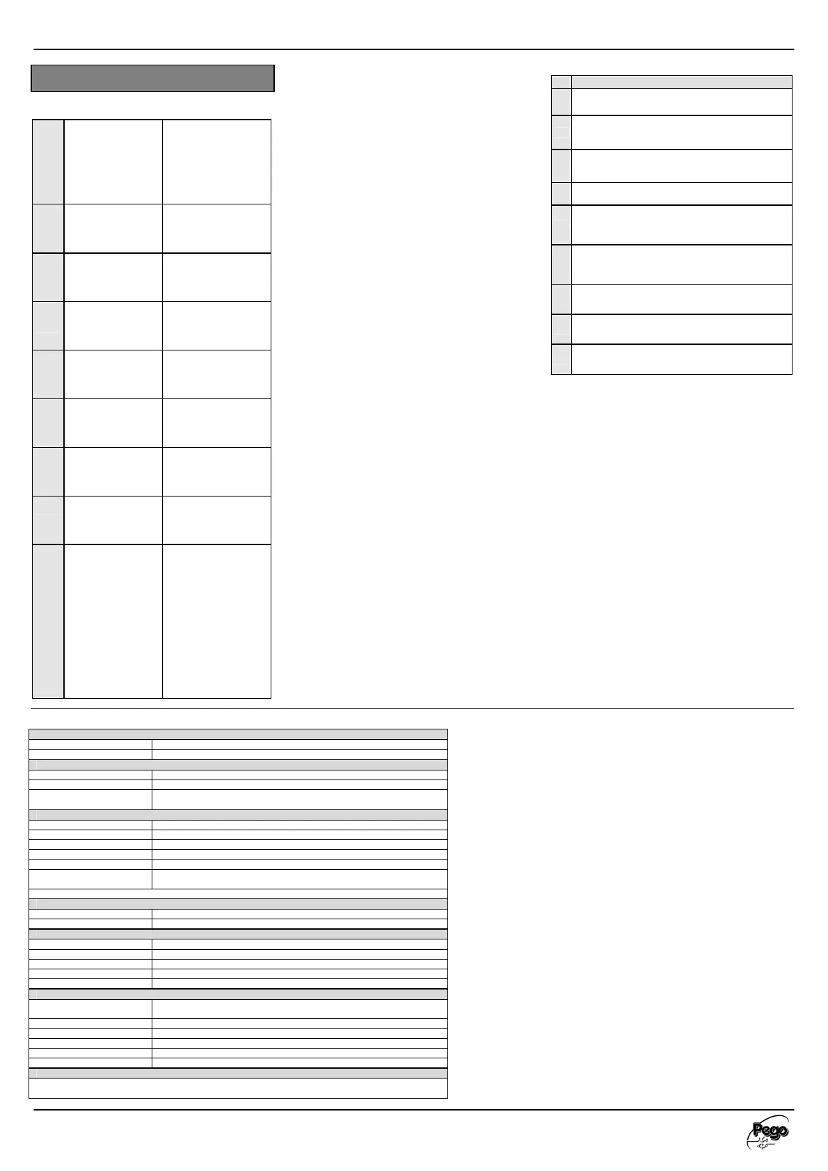
ALARM CODE TABLE
Var
E0 Functional fault of ambient probe.
E1
Functional fault of defrosting probe (in this case, any defrosting
processes will have a duration equal to time d3).
E2
EEPROM memory error. All outputs are deactivated except for
alarm outputs if present.
E8
Man-in-room alarm.
Ec
Compressor protection alarm (e.g. thermal protection or max.
pressure switch). All outputs are deactivated except for the
alarm output if present.
Ed
Door open alarm. When the door switch opens and the tdo
time has elapsed, normal function of the control is reset,
triggering the door open alarm (Ed).
EL
Minimum temperature alarm. The letters EL flash alternating
with the temperature (see parameter A1).
EH
Maximum temperature alarm. The letters EH flash alternating
with the temperature (see parameter A2).
E9
Room light alarm. The letters E9 flash alternating with the
temperature (see parameter dO2 and Tdo).
VARIABLE LIST HACCP LEVEL
(Values in read-only)
E##
Indicates the latest
activated
temperature alarm.
EH = high temperature
alarm
EL = low temperature
alarm
-- = no alarms have been
activated from the latest
reset
###
Temperature peak
value reached during
the latest EH or EL
alarm
-45…+45°C
--- = no alarms have been
activated from the latest
reset
y##
Year of the start of
the lastest
temperature alarm
y 00 – y99
y -- = no alarms have been
activated from the latest
reset
M##
Month of the start of
the lastest
temperature alarm
M 01 – M12
M --
activated from the latest
reset
d##
Day of the start of the
lastest temperature
alarm
d 01 – d31
d -- = nessun allarme
intervenuto dall’ultimo
reset
h##
Hour of the start of
the lastest
temperature alarm
h 00 – h24
h -- = no alarms have been
activated from the latest
reset
m##
Minutes of the start
of the lastest
temperature alarm
m 00 – m59
m -- = no alarms have been
activated from the latest
reset
t##
Duration (hours) of
the latest
temperature alarm
t 00 – t99
t -- = no alarms have been
activated from the latest
reset
C##
Contactor of the nr of
temperature alarm events
occurred (being
memorised data of the
latest temperature alarm
event, the contactor is
boosted to know if
previously other alarms
occurred)
. This contactor resets with
the memorised alarm reset
(silenced button + SET for 5
sec.) It is implemented at
every new temperature
alarm.)
C 00 – C99
C -- = no alarms have been
activated from the latest reset
humidity < 90% Rel. Hum. N
humidity < 90% Rel. Hum. Not condensing
Environments with strong vibrations or impacts; aggressive, polluted or corrosive
atmospheres, exposure to direct solar radiation, explosive atmospheres or flammable gas.
Digit with sign, decimal point and 9 LED status indicators
Probe precision (electronic)
Connector for temperature r
, screw for cables with c/section 0.2 to 2.5mm
, screw for cables with c/section 0.2 to 1.5mm
2
Software class: A / Parameters saved on non
2 Inputs for NTC probes (10K Ώ 1% at 25°C)
Dimensional, insulation and mechanical characteristics
Dimensions
(Depth 69mm with removable clamps)
In front of board by means of rear fastening clips or or two front screws
0 body, PC transparent front, Key panel PC or PC+ABS
Conformity with EEC low voltage direc
tives, electromagnetic compatibility and EC mark
Conforms to following EEC Directives : Directives 2004/108/EEC , 2006/95/EEC, 93/68 EEC
Conforms to following harmonised standards: EN60730
 Loading...