PressureMAT User Guide
Revision 1
Page 8/29
CONNECTIONS:
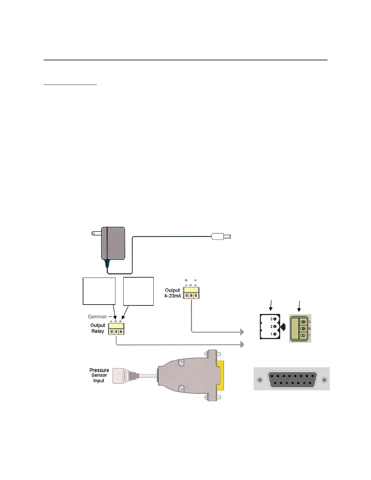
The external connections to the back panel are as shown below.
1. POWER SUPPLY connected to the power inlet connector
2. The PRESSURE SENSOR INPUTS connected via the DB15 connector
3. The OUTPUT RELAY:
a. NORMALLY OPEN- wired to terminals S and T via supplied connector (will switch to
CLOSED position with alarm condition)
b. NORMALLY CLOSED- wired to terminals R and T via supplied connector (will
switch to OPEN position with alarm condition)
c. POWER REMOVED- OPEN (S and T position) is the condition for relay(s)
4. The 4-20mA ANALOG OUTPUTS are wired to terminals S and T via supplied connector as
shown.
External Cable Connections to Back Panel
To Power Inlet Connector
___________________
Panel Connector
_____________________
To Pressure Sensor Inputs
(DB15)
Wire here
for
Normally
CLOSED
Wire here
for
Normally
OPEN