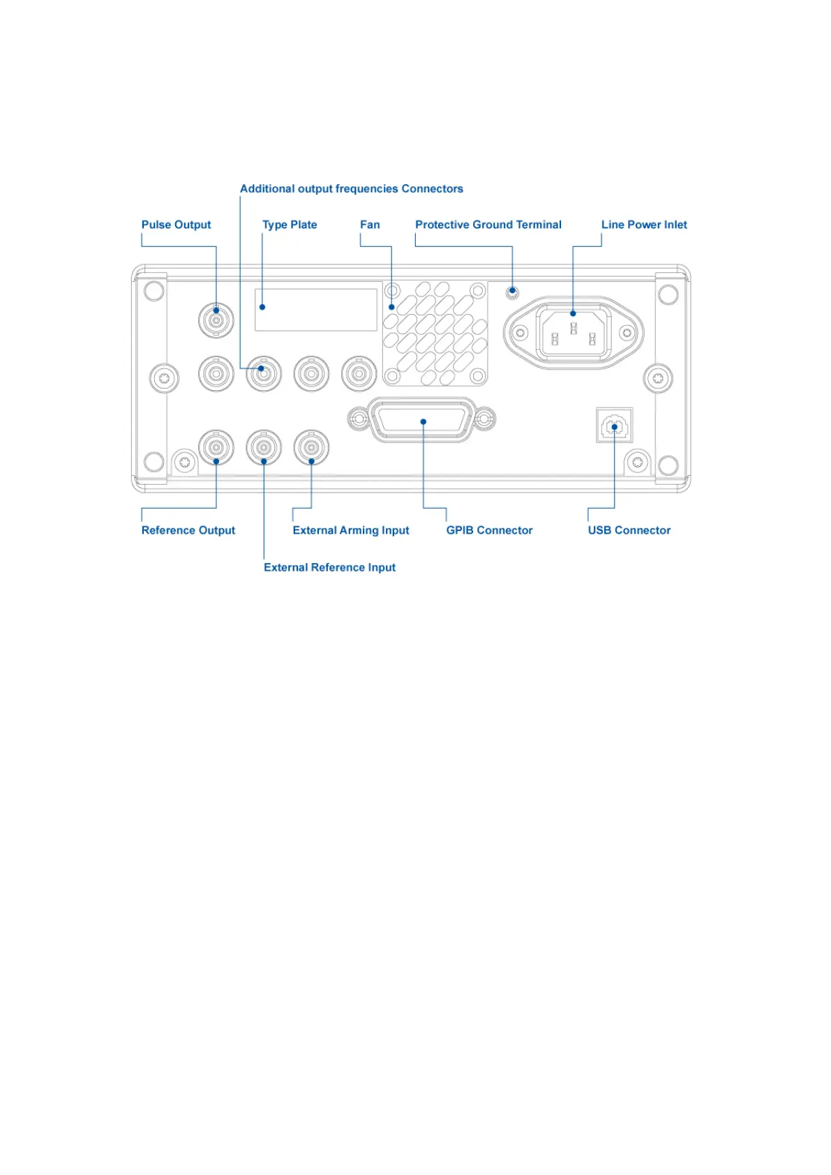
3.2.3. Rear Panel (CNT-91R/AF)
Pulse Output [CNT-91(R) only]: User definable to serve as output for built-in pulse generator, gate indicator or alarm.
Additional output frequencies Connectors: These connectors provide additional output frequencies which are, from
left to right, 100kHz, 1MHz, 5MHz and 10MHz.
Type Plate: Indicates instrument type and serial number.
Fan: A temp. sensor controls the speed of the fan. Normal bench-top use means low speed, whereas rack-mounting
and/or options may result in higher speed.
Protective Ground Terminal: This is where the protective ground wire is connected inside the instrument. Never
tamper with this screw!
Line Power Inlet: AC 90-265 Vrms, 45-440 Hz, no range switching needed.
Reference Output: 10 MHz derived from the internal or, if present, the external reference.
External Reference Input: Can be automatically selected if a signal is present and approved as timebase source, see
Chapter 9.
External Arming Input: See page 5-7.
GPIB Connector: Address set via User Options Menu.
USB Connector: Universal Serial Bus (USB) for data communication with PC.
17 / 50

 Loading...