2.3.1. Check List
The shipment should contain the following:
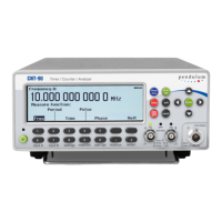
Counter/Timer/Analyzer CNT-90/91 or Frequency Calibrator/Analyzer CNT-91R or CNT-91R/AF or
Microwave Counter/Analyzer CNT-90XL
Line cord
Brochure with Important Information
Certificate of Calibration
Options you ordered should be installed. See Identification below.
CD including the following documentation in PDF:
Getting Started Manual
User’s Manual
Programmer’s Handbook
2.3.2. Identification
The type plate on the rear panel shows type number and serial number. See illustrations on page 2-5 and 2-6. Installed
options are listed under the menu User Options – About, where you can also find information on firmware version and
calibration date. See page 2-15. The CNT-91R/AF version is identified by a unique identification marking, or UID. This
permanent tag contains a barcode and allows customers to track easily their inventory and property.
2.3.3. Installation
2.3.3.1. Supply Voltage
Setting
The Counter may be connected to any AC supply with a voltage rating of 90 to 265 Vrms, 45 to 440 Hz. The counter
automatically adjusts itself to the input line voltage.
Fuse
The secondary supply voltages are electronically protected against overload or short circuit. The primary line voltage
side is protected by a fuse located on the power supply unit. The fuse rating covers the full voltage range.
Consequently, there is no need for the user to replace the fuse under any operating conditions, nor is it accessible from
the outside.
CAUTION: If this fuse is blown, it is likely that the power supply is badly
damaged. Do not replace the fuse. Send the counter to the local Service
Center.
Removing the cover for repair, maintenance and adjustment must be done by qualified and trained personnel only, who
are fully aware of the hazards involved.
The warranty commitments are rendered void if unauthorized access to the
interior of the instrument has taken place during the given warranty period.
2.3.3.2. Battery Supply
CNT-90 & CNT-90XL only
7 / 50

 Loading...