• Do not mount the controller on surfaces that are prone
to vibration.
• Do not mount the controller in a location where high-
voltage relays, motor starters, and other sources of
electromagnetic emissions or strong radio frequency
may cause electromagnetic interference (EMI).
• Do not install the controller in airtight enclosures.
• Do not install heat generating devices with the
controller in an enclosure that may cause the ambient
temperature to exceed 60°C (140°F).
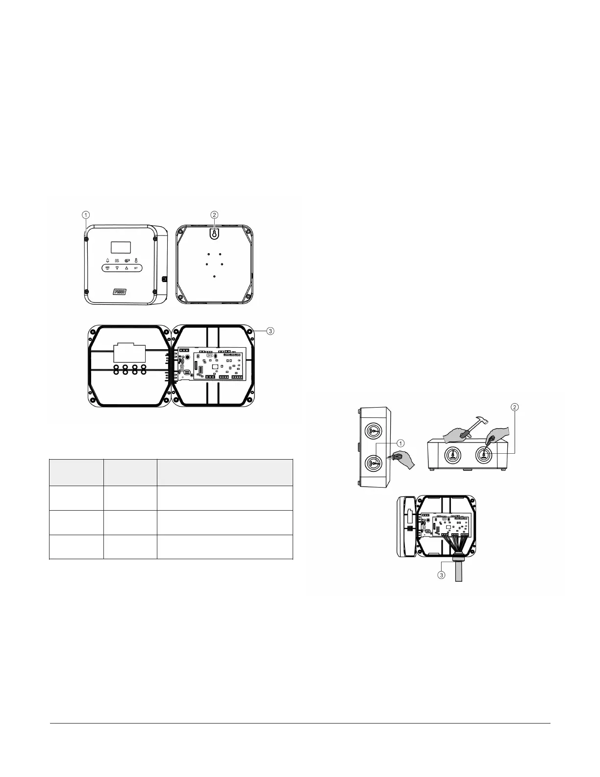
Figure 2: A525 Fermentation Controller wall and
surface mounting
Table 1: A525 Fermentation Controller wall and surface
mounting callout table
Callout
Controller
view
Description
1
Front view Spring-loaded cover screw on
the controller cover
2
Rear view Keyhole slot on the rear of the
enclosure base
3
Interior
right view
Mounting screw hole on the
enclosure base
Mounting the controller on a wall or flat
surface
To mount the A525 Fermentation Controller on a wall or
other flat surface, complete the following steps:
1. To open the controller cover, loosen the four spring-
loaded cover screws. Be careful not to damage the
controller’s interior components.
2. Attach an appropriate fastener onto the wall or other
flat surface.
3. Position the keyhole slot on the rear of the enclosure
base over the fastener. Make sure that the controller
hangs securely on the fastener.
4. Use the four holes on the corners of the enclosure
base to mark the location for the mounting screws.
Remove the keyhole slot fastener from the wall or flat
surface.
5. Use four screws to mount the controller: M4 (#8)
pan-head screw; 12 mm (0.5 in.) or longer.
6. Tighten the screws. Use shims to prevent warping the
enclosure.
7. To seal the cover, close the front cover and tighten
the spring-loaded cover screws to 0.9–1.1 N·m (8–10
in·lbs).
DIN rail mounting
You can optionally order a DIN rail mount kit (BKT524-1K)
for the A525 Fermentation Controller. Attach the DIN rail
clip assembly to the five holes on the rear of the enclosure
base.
Refer to the installation instructions included with the DIN
rail kit for DIN rail mounting procedures.
Conduit plug removal and liquid
tight fitting
The following figure shows how to remove the conduit
plug and insert the liquid tight fitting.
Figure 3: Conduit plug removal and liquid tight fitting
Removing the conduit plug and inserting
the liquid tight fitting
To remove the conduit plug and insert the liquid tight
fitting, complete the following steps:
1. Use a cutting pliers to clip the conduit rib.
A525 Fermentation Tank Controller Installation Guide2

 Loading...