Low-voltage wiring
The following figure and table provide information about the low-voltage wiring terminal blocks, wiring terminal labels,
and required wire sizes.
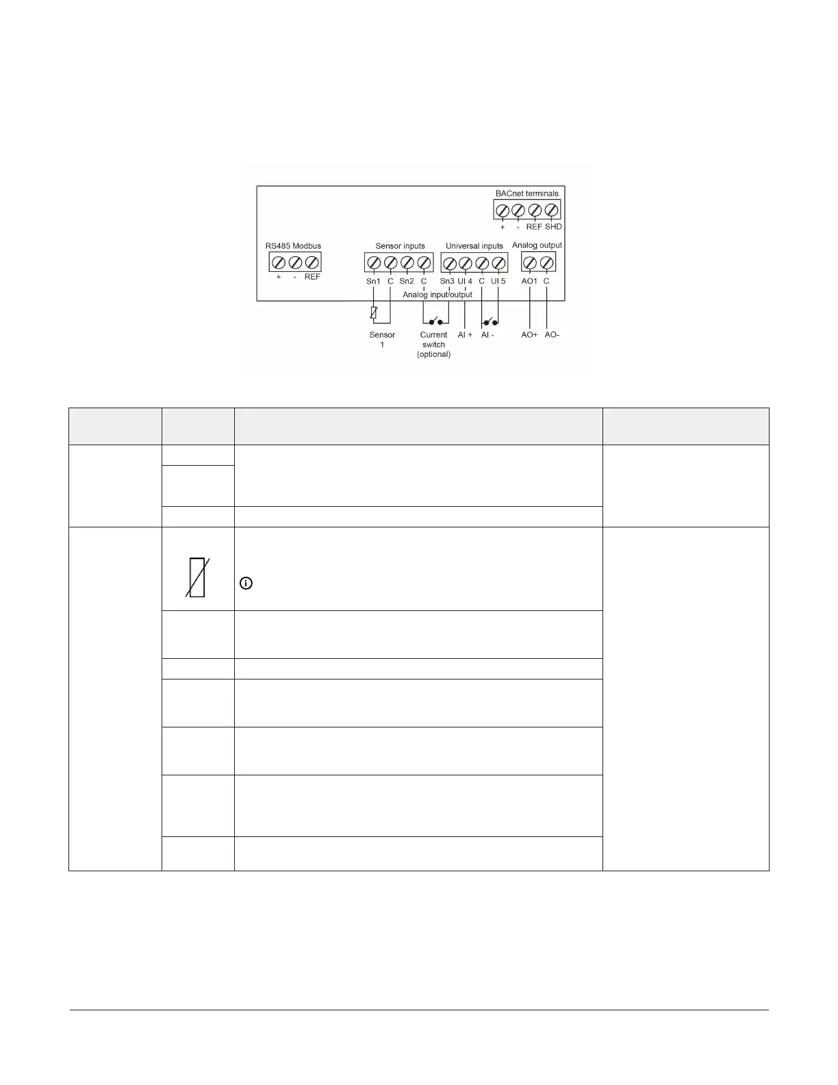
Figure 4: A525 Controller low-voltage terminal block connections (internal to control)
Table 2: A525 Controller low-voltage terminal block, terminals, and wire sizes
Terminal
block label
Terminal
label
Description, function, and requirements Required wire sizes
+
-
The RS485 Modbus communications terminal block is
restricted to an optional variable-frequency drive (VFD) that
is used to control pump-over operations. Do not connect
another Modbus device to these terminals.
RS485
Modbus
REF The RS485 Modbus signal common or reference
• 0.20 mm
2
– 0.30 mm
2
• (26 AWG–22 AWG)
• Stranded wires and
twisted-leads cable
Sn1
Sensor 1 (Sn1) is the main tank temperature sensor. Connect
either lead from the sensor to Sn1. Connect the other lead to
a common (C) terminal.
Note: Sensor wires for the A525 Controller are not
polarity sensitive.
C
The A525 Fermentation Controller includes four low-voltage
common terminals. All of the low-voltage C terminals are
connected together on the PC board.
Sn2 Sensor 2 (Sn2) is unused.
Sn3
You can use Sensor 3 (Sn3) with a current switch. The current
switch monitors the status of the pump motor. This is an
optional feature.
UI 4
You can use Universal Input 4 (UI 4) to monitor the speed of
a pump motor if the VFD provides this output signal to the
control. This is an optional feature.
UI 5
You can use Universal Input 5 (UI 5) to connect a remote
pump start or stop button. This input is intended for a
momentary push-button and can start or stop a pump-over.
This is an optional feature.
Analog input/
output
AO 1
AO 1 sets the speed of the VFD (0 V-10 V). This is an optional
feature.
• 0.30 mm
2
–1.50 mm
2
• (22 AWG–16 AWG)
• Stranded wires and
twisted-leads cable
A525 Fermentation Tank Controller Installation Guide4

 Loading...