P78 Series Controls for Dual Pressure Applications Installation Instructions
7
Table 3: Adjusting P78 Dual Pressure Controls
Manual Reset Operation
Pressure controls with the Manual Reset option, lock out when they reach Cut-out pressure and must be manually
reset by the user to restart the controlled equipment. The manual reset mechanism is trip-free and cannot be
overridden by holding the Reset Button down.
When a control requires a manual reset, first determine what caused the control to cut out, and allow the sensed
pressure to fall at least 44 psi (3 bar) below the Cut-out pressure. Then press and release the Reset Button on the
front of the control to restore normal operation of the controlled equipment (see Item 5, Figure 4).
Technical Specifications
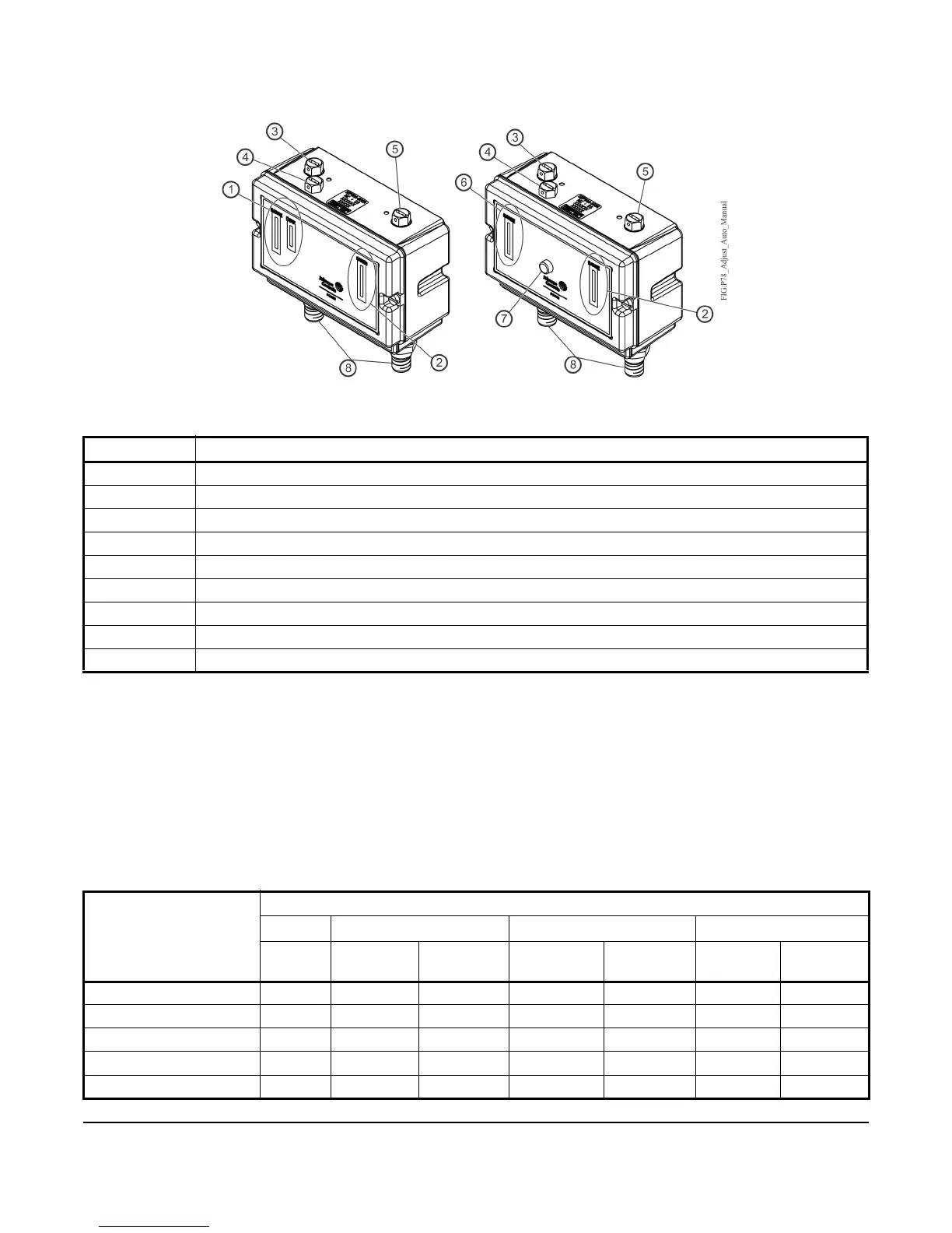
Callout Description
1 Low Side Range and Differential Scales
2 High Side Range Scale
3 Low Side Range Screw
4 Low Side Differential Screw
5 High Side Range Screw
6 Low Side Range Scale (only)
7 Reset Button
8 Pressure Connection
9 Adjustment Lock Plate (if applied)
Table 4: P78 Series Electrical Ratings
Volts AC 50/60 Hz
UL60730
24 120 208 240
– Primary
Contact
Secondary
Contact
Primary
Contact
Secondary
Contact
Primary
Contact
Secondary
Contact
Horsepower – 1 .33 1 0.75 1 1
Full Load Amperes – 16 7.2 9.2 7.6 8 8
Locked Rotor Amperes – 96 43.2 55.2 45.6 48 48
Resistive Amperes 16/8 16 8 10 8 10 8
Pilot Duty VA 125/125 720 720 720 720 720 720
Note: The Primary Contact is A–C; the Secondary Contacts are A–B and A–D.
Figure 4: Adjusting the P78 Dual Pressure Controls
Manual Reset Lockout
Automatic Reset

 Loading...