P78 Series Controls for Dual Pressure and Hazardous Location Applications Installation Guide
7
Adjusting the P78 Dual Pressure Controls
Use the following procedures for adjusting these controls. Refer to the product label inside the control cover for
model number and switch action.
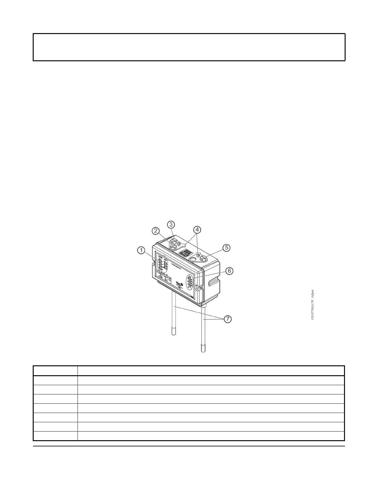
Dual pressure with automatic reset: Models with automatic reset have a scaleplate that displays the cut-in and
differential setpoints for the low side (Callout 1, Figure 6). The high side scaleplate of the P78 dual pressure control
displays only the cut-out setpoint (6).
1. Set the low side cut-in setpoint (high event; A closes to C) by adjusting the range screw.
2. Turn the low side range screw (Callout 3) clockwise to raise the cut-in setpoint.
3. Set the cut-out setpoint (low event; A opens to C) by adjusting the differential screw (Callout 2).
4. Turn the differential screw clockwise to raise the cut-out setpoint.
Note: For the low side: cut-out equals cut-in minus differential.
5. Set the high side cut-out setpoint (high event, A opens to B) by adjusting the range screw.
6. Turn the high side range screw (Callout 5) clockwise to raise the cut-out setpoint.
7. Mount the adjustment lock plates.
Note: The pressure must drop 3 bar below the high-pressure cutout setpoint to reset the switch.
IMPORTANT: Do not adjust pointers beyond the highest or lowest indicator marks on the control’s pressure
scale. Adjusting pointers beyond indicator marks may damage screw threads, may cause inaccurate control
operation, and will void the warranty.
Table 5: Adjusting P78 Dual Pressure Controls
Callout Description
1 Low Side Range and Differential Scales
2 Low Side Differential Screw
3 Low Side Range Screw
4 Adjustment Lock Plates
5 High Side Range Screw
6 High Side Range Scale
7 Pressure Connections
Figure 6: Adjusting the P78 Dual Pressure Controls

 Loading...