P78 Series Controls for Dual Pressure and Hazardous Location Applications Installation Guide
6
The selected associated apparatus providing output entity parameters must be third-party listed for the application,
and have intrinsically safe entity parameters that conform with the guidelines set out in the following table.
Calculate the capacitance and inductance of the field wiring from intrinsically safe equipment to the associated
apparatus and include them in the system calculations as shown in the previous table. Cable capacitance, Ccable,
plus intrinsically safe equipment capacitance, Ci, must be less than the marked capacitance, Ca (or Co), shown in
any associated apparatus used. The same applies for inductance (Lcable, Li and La or Lo, respectively). If you do
not know the cable capacitance and inductance per meter (foot), use the following values:
Ccable = 60 pF per 30 cm (1 ft), Lcable = 0.2 µH per 30 cm (1 ft)
If you do not know the Po of the associated apparatus, calculate it using the following formula:
Po = (Voc x Isc)/4 = (Uo x Io)/4
Install the associated apparatus in accordance with its manufacturer’s control drawing and the
ATEX Directive for installation in Europe, UKEx regulations in the UK, Article 504 of the National Electrical Code
(ANSI/NFPA 70) for installation in the United States, or Section 18 of the Canadian Electrical Code for installation in
Canada, and all other applicable codes.
You can use the associated apparatus in a Group II, Zone 2 or Class I, Division 2 location if the apparatus is
approved for the area.
Refrigerant connections
P78 dual pressure controls are connected to the controlled equipment by a 6 mm diameter copper tube solder
connection to ensure a hermetic installation.
Avoid severe pressure pulsations at high-side pressure connections. Install pressure connection to pressure-tap
points away from the compressor to minimize the effects of pressure pulsations from reciprocating compressors.
Setup and adjustments
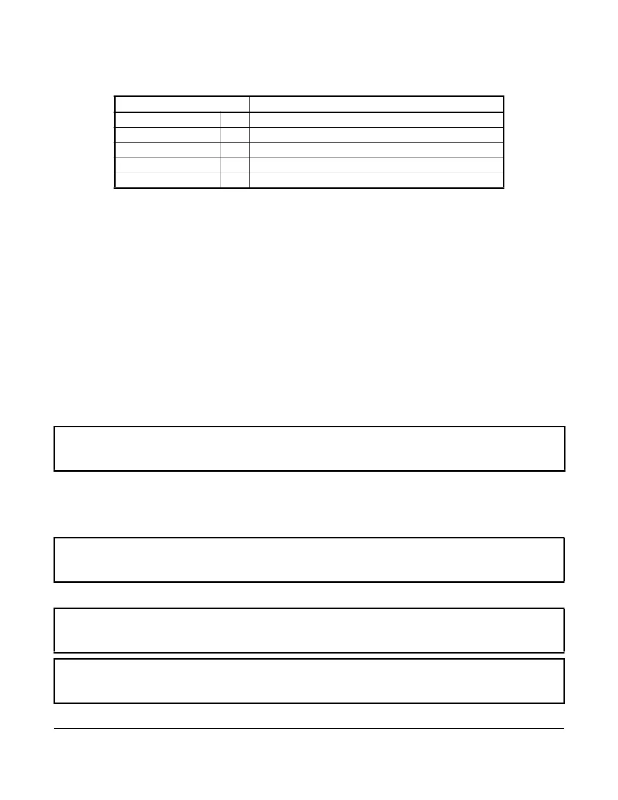
Table 4: Intrinsically safe entity parameters for the associated apparatus
P78 Pressure Control Zener Barrier or suitable associated apparatus
Ui Max (V max) ≥ Voc or Vt (or Uo)
Ii Max (I max) ≥ Isc or It (or Io)
Pi max (P max) ≥ Po
Ci + Ccable ≤ Ca (or Co)
Li + Lcable ≤ La (or Lo)
IMPORTANT: If the control is installed on equipment that contains hazardous or regulated materials such as
certain refrigerants or lubricants, you must comply with all standards and regulations governing the containment
and handling of those materials.
IMPORTANT: After installing the control, evacuate the refrigerant pressure connection lines to remove air,
moisture, and other contaminants in a manner consistent with applicable environmental regulations and
standards.
IMPORTANT: Use the pressure control settings recommended by the manufacturer of the controlled
equipment. Do not exceed the pressure ratings of the controlled equipment or any of its components when
checking pressure control operation or operating the controlled equipment.
IMPORTANT: After installing the control, attach a reliable set of gauges to the controlled equipment, and
operate the equipment for at least three cycles at the pressures necessary to verify control setpoints and proper
equipment operation.

 Loading...